
Computer Networks
Click here to view ALL computer networks classes
https://youtube.com/playlist?list=PLudAlUAn-WWS_W_djRqa2VFhXEBVbxJ7v
UNIT – I
Introduction to Computer Networks, Network Hardware and Software, Network Standardization Protocols and Standards, OSI and TC/IP Reference Models, Example Networks.
The Physical Layer: Guided Transmission Media, Wireless Transmission, Communication Satellites, Circuit switched networks, Datagram networks, virtual circuit networks, The Mobile Telephone System.
UNIT – II
The Data Link Layer:Data link layer design issues, framing techniques, error control methods, flow control over noiseless and noisy channels, Example data link protocols. The Medium Access Control Sublayer: The Channel Allocation Problem, Carrier Sense Multiple Access Protocols, Collision free protocols, IEEE Ethernet, Wireless LANs, Bluetooth, Data Link Layer Switching.
UNIT – III
The Network Layer: Network Layer Design Issues, Datagram and Virtual circuit subnets, Routing Algorithms, Multicast Routing Algorithms, Routing in Adhoc networks, Congestion Control Algorithms, Quality of Service, Internetworking, and The Network Layer in the Internet: IPv4 IPv6 and IP Addresses.
UNIT – IV
The Transport Layer: The Transport Service, Elements of Transport Protocols, TCP connection establishment, A Simple Transport Protocol, UDP, and TCP Protocols, The Internet Transport Protocols: TCP
UNIT – V
The Application Layer: DNS—The Domain Name System, Electronic Mail, MIME, SMTP protocol, PoP3, IMAP, The World Wide Web, URLs, HTM and Multimedia. Network Security: Cryptography, Symmetric-Key Algorithms, Public-Key Algorithms.

Introduction to Networks
A computer network is a system that connects numerous independent computers in order to share information (data) and resources. The integration of computers and other different devices allows users to communicate more easily.
A computer network is a collection of two or more computer systems that are linked together. A network connection can be established using either cable or wireless media. Hardware and software are used to connect computers and tools in any network.
A computer network consists of various kinds of nodes. Servers, networking hardware, personal computers, and other specialized or general-purpose hosts can all be nodes in a computer network. Hostnames and network addresses are used to identify them.
Criteria of good network:
- Performance: It can be measured in many ways, including transmit time and response time. Transit time is the amount of time required for a message to travel from one device to another. Response time is the elapsed time between an inquiry and a response. The performance of the network depends on a number of factors, including the number of users, the type of medium & hardware
- Reliability: In the addition to accuracy is measured by frequency of failure, the time it takes a link to recover from failure, and the network’s robustness in catastrophe.
- Security: Network security issues include protecting data from unauthorized access, protecting data from damage and development, and implementing policies and procedures for recovery from breaches and data loss.
Goal Of Networking:
- Programs do not have to execute on a single system because of resource and load sharing.
- Reduced costs – Multiple machines can share printers, tape drives, and other peripherals.
- Reliability – If one machine fails, another can take its place.
- Scalability (it’s simple to add more processors or computers)
- Communication and mail (people living apart can work together)
- Information Access (remote information access, access to the internet, e-mail, video conferencing, and online shopping)
- Entertainment that is interactive (online games, videos, etc.)
- Social Networking
Types of Networks
Division based on the communication medium
- Wired Network: As we all know, “wired” refers to any physical medium made up of cables. Copper wire, twisted pair, or fiber optic cables are all options. A wired network employs wires to link devices to the Internet or another network, such as laptops or desktop PCs.
- Wireless Network: “Wireless” means without wire, media that is made up of electromagnetic waves (EM Waves) or infrared waves. Antennas or sensors will be present on all wireless devices. Cellular phones, wireless sensors, TV remotes, satellite disc receivers, and laptops with WLAN cards are all examples of wireless devices. For data or voice communication, a wireless network uses radio frequency waves rather than wires.
Division based on area covered
- Local Area Network (LAN): A LAN is a network that covers an area of around 10 kilometers. For example, a college network or an office network. Depending upon the needs of the organization, a LAN can be a single office, building, or Campus. We can have two PCs and one printer in-home office or it can extend throughout a company and include audio and video devices. Each host in LAN has an identifier, an address that defines hosts in LAN. A packet sent by the host to another host carries both the source host’s and the destination host’s address.
- Metropolitan Area Network (MAN): MAN refers to a network that covers an entire city. For example: consider the cable television network.
- Wide Area Network (WAN): WAN refers to a network that connects countries or continents. For example, the Internet allows users to access a distributed system called www from anywhere around the globe.WAN interconnects connecting devices such as switches, routers, or modems. A LAN is normally privately owned by an organization that uses it. We see two distinct examples of WANs today: point-to-point WANs and Switched WANs
Point To Point: Connects two connecting devices through transmission media.
Switched: A switched WAN is a network with more than two ends.
Based on types of communication
- Point To Point networks: Point-to-Point networking is a type of data networking that establishes a direct link between two networking nodes.
A direct link between two devices, such as a computer and a printer, is known as a point-to-point connection. - Multipoint: is the one in which more than two specific devices share links. In the multipoint environment, the capacity of the channel is shared, either spatially or temporally. If several devices can use the link simultaneously, it is a spatially shared connection.
- Broadcast networks: In broadcast networks, a signal method in which numerous parties can hear a single sender. Radio stations are an excellent illustration of the “Broadcast Network” in everyday life. The radio station is a sender of data/signal in this scenario, and data is only intended to travel in one direction. Away from the radio transmission tower, to be precise.
Based on the type of architecture
- P2P Networks: Computers with similar capabilities and configurations are referred to as peers.
“Peer to Peer” is the abbreviation for “peer to peer.” The “peers” in a peer-to-peer network are computer systems that are connected to each other over the Internet. Without the use of a central server, files can be shared directly between systems on the network. - Client-Server Networks: Each computer or process on the network is either a client or a server in a client-server architecture (client/server). The client asks for services from the server, which the server provides. Servers are high-performance computers or processes that manage disc drives (file servers), printers (print servers), or network traffic (network servers)
- Hybrid Networks: The hybrid model refers to a network that uses a combination of client-server and peer-to-peer architecture. Eg: Torrent.
Network Topology
1. Bus Topology: Every computer and network device is connected to a single cable in a bus topology network. Linear Bus topology is defined as having exactly two terminals.
Advantages
- Installation is simple.
- Compared to mesh, star, and tree topologies, the bus utilizes less cabling.
Disadvantages
- Difficulty in reconfiguring and isolating faults.
- A bus cable malfunction or break interrupts all communication.
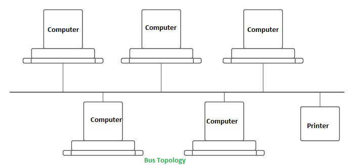
https://youtu.be/OYc13nF5HqQ
2. Ring Topology: The topology is named ring topology because one computer is connected to another, with the final one being connected to the first. Exactly two neighbors for each device. A signal is passed along the ring in one direction. Each ring incorporates a repeater.
Advantages
- Data transmission is relatively straightforward because packets only move in one direction.
- There is no requirement for a central controller to manage communication between nodes.
- Easy installation & Reconfiguration
- Simplified Faulty connections
Disadvantages
- In a Unidirectional Ring, a data packet must traverse through all nodes.
- All computers must be turned on in order for them to connect with one another.
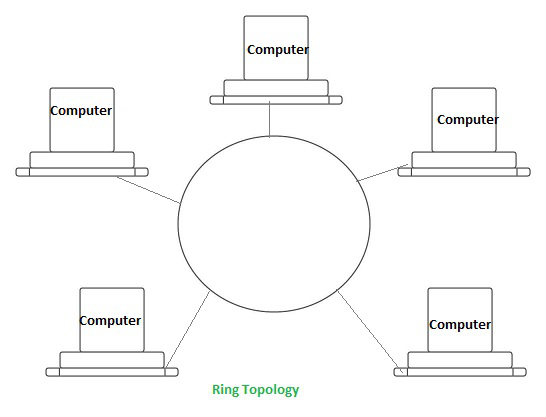
https://youtu.be/BzWfTmxIByE
3. Star Topology: Each device in a star topology has a dedicated point-to-point link to a central controller, which is commonly referred to as the HUB. There is no direct connection between the devices. Traffic between the devices is not allowed in this topology. As an exchange, the controller is used.
Advantages
- When attaching or disconnecting devices, there are no network interruptions.
- It’s simple to set up and configure.
- Identifying and isolating faults is simple.
- Less Expensive than mesh
- Easy to install & configure
Disadvantages
- Nodes attached to the hub, switch, or concentrator is failed if they fail.
- Because of the expense of the hubs, it is more expensive than linear bus topologies.
- More cable required compared to bus or ring
- Too much dependency on Hub
Example: Used in high-speed LANs
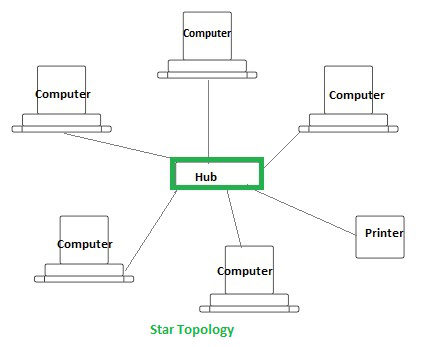
https://youtu.be/ipL9vp_nlA8
4. Mesh Topology: Every device in a mesh topology has dedicated point-to-point connectivity to every other device. The term “dedicated” refers to the fact that the link exclusively transports data between the two devices it links. To connect n devices, a fully connected mesh network contains n *(n-1)/2 physical channels.
Advantages
- Data can be sent from multiple devices at the same time. This topology can handle a lot of traffic.
- Even if one of the connections fails, a backup is always available. As a result, data transit is unaffected.
- Physical boundaries prevent other users from gaining access to messages
- Point to Point links make fault transmission & fault isolation easy
Disadvantages
- The amount of cabling and the number of I/O ports that are necessary.
- The sheer bulk of wiring can be greater than the available space can accommodate.
- It is difficult to install and reconfigure.
Example: connection of telephone regional office in which each regional office needs to be connected to every other regional office.
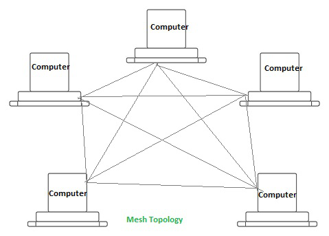
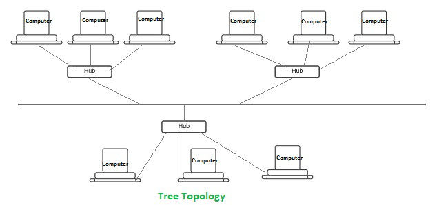
5. Tree Topology: The topology of a tree is similar to that of a star. Nodes in a tree, like those in a star, are connected to a central hub that manages network traffic. It has a root node, which is connected to all other nodes, producing a hierarchy. Hierarchical topology is another name for it. The number of Star networks is connected via Bus in Tree Topology.
Advantages
- Network expansion is both possible and simple.
- We partition the entire network into pieces (star networks) that are easier to manage and maintain.
- Other segments are unaffected if one segment is damaged.
Disadvantages
- Tree topology relies largely on the main bus cable because of its basic structure, and if it fails, the entire network is handicapped.
- Maintenance becomes more challenging when more nodes and segments are added.
Video 6 - Mesh topology
https://youtu.be/Ju8qrA5IUUM
Networking Devices
Basic hardware interconnecting network nodes, such as Network Interface Cards (NICs), Bridges, Hubs, Switches, and Routers, are used in all networks. In addition, a mechanism for connecting these building parts is necessary, which is usually galvanic cable and optical cable are less popular (“optical fiber”)The following are the network devices :
- NIC (Network Interface Card): A network card, often known as a network adapter or NIC (network interface card), is computer hardware that enables computers to communicate via a network. It offers physical access to networking media and, in many cases, MAC addresses serve as a low-level addressing scheme. Each network interface card has a distinct identifier. This is stored on a chip that is attached to the card.
- Repeater: A repeater is an electrical device that receives a signal, cleans it of unwanted noise, regenerates it, and retransmits it at a higher power level or to the opposite side of an obstruction, allowing the signal to travel greater distances without degradation. In the majority of twisted pair Ethernet networks, Repeaters are necessary for cable lengths longer than 100 meters in some systems. Repeaters are based on physics.
- Hub: A hub is a device that joins together many twisted pairs or fiber optic Ethernet devices to give the illusion as a formation of a single network segment. The device can be visualized as a multiport repeater. A network hub is a relatively simple broadcast device. Any packet entering any port is regenerated and broadcast out on all other ports, and hubs do not control any of the traffic that passes through them. Packet collisions occur as a result of every packet being sent out through all other ports, substantially impeding the smooth flow of communication.
- Bridges: Bridges broadcast data to all the ports but not on the one that received the transmission. Bridges, on the other hand, learn which MAC addresses are reachable through specific ports rather than copying messages to all ports as hubs do. Once a port and an address are associated, the bridge will only transport traffic for that address to that port.
- Switches: A switch differs from a hub in that it only forwards frames to the ports that are participating in the communication, rather than all of the ports that are connected. The collision domain is broken by a switch, yet the switch depicts itself as a broadcast domain. Frame forwarding decisions are made by switches based on MAC addresses.
- Routers: Routers are networking devices that use headers and forwarding tables to find the optimal way to forward data packets between networks. A router is a computer networking device that links two or more computer networks and selectively exchanges data packets between them. A router can use address information in each data packet to determine if the source and destination are on the same network or if the data packet has to be transported between networks. When numerous routers are deployed in a wide collection of interconnected networks, the routers share target system addresses so that each router can develop a table displaying the preferred pathways between any two systems on the associated networks.
- Gateways: To provide system compatibility, a gateway may contain devices such as protocol translators, impedance matching devices, rate converters, fault isolators, or signal translators. It also necessitates the development of administrative procedures that are acceptable to both networks. By completing the necessary protocol conversions, a protocol translation/mapping gateway joins networks that use distinct network protocol technologies.
- Transmission Control Protocol (TCP): TCP is a popular communication protocol which is used for communicating over a network. It divides any message into series of packets that are sent from source to destination and there it gets reassembled at the destination.
- Internet Protocol (IP): IP is designed explicitly as addressing protocol. It is mostly used with TCP. The IP addresses in packets help in routing them through different nodes in a network until it reaches the destination system. TCP/IP is the most popular protocol connecting the networks.
- User Datagram Protocol (UDP): UDP is a substitute communication protocol to Transmission Control Protocol implemented primarily for creating loss-tolerating and low-latency linking between different applications.
- Post office Protocol (POP): POP3 is designed for receiving incoming E-mails.
- Simple mail transport Protocol (SMTP): SMTP is designed to send and distribute outgoing E-Mail.
- File Transfer Protocol (FTP): FTP allows users to transfer files from one machine to another. Types of files may include program files, multimedia files, text files, and documents, etc.
- Hyper Text Transfer Protocol (HTTP): HTTP is designed for transferring a hypertext among two or more systems. HTML tags are used for creating links. These links may be in any form like text or images. HTTP is designed on Client-server principles which allow a client system for establishing a connection with the server machine for making a request. The server acknowledges the request initiated by the client and responds accordingly.
- Hyper Text Transfer Protocol Secure (HTTPS): HTTPS is abbreviated as Hyper Text Transfer Protocol Secure is a standard protocol to secure the communication among two computers one using the browser and other fetching data from web server. HTTP is used for transferring data between the client browser (request) and the web server (response) in the hypertext format, same in case of HTTPS except that the transferring of data is done in an encrypted format. So it can be said that https thwart hackers from interpretation or modification of data throughout the transfer of packets.
- Telnet: Telnet is a set of rules designed for connecting one system with another. The connecting process here is termed as remote login. The system which requests for connection is the local computer, and the system which accepts the connection is the remote computer.
- Gopher: Gopher is a collection of rules implemented for searching, retrieving as well as displaying documents from isolated sites. Gopher also works on the client/server principle.
Some other popular protocols act as co-functioning protocols associated with these primary protocols for core functioning. These are:
- ARP (Address Resolution Protocol)
- DHCP (Dynamic Host Configuration Protocol)
- IMAP4 (Internet Message Access Protocol)
- SIP (Session Initiation Protocol)
- RTP (Real-Time Transport Protocol)
- RLP (Resource Location Protocol)
- RAP (Route Access Protocol)
- L2TP (Layer Two Tunnelling Protocol)
- PPTP (Point To Point Tunnelling Protocol)
- SNMP (Simple Network Management Protocol)
- TFTP (Trivial File Transfer Protocol)
Physical Layer in OSI Model
Physical Layer is the bottom-most layer in the Open System Interconnection (OSI) Model which is a physical and electrical representation of the system. It consists of various network components such as power plugs, connectors, receivers, cable types, etc. Physical Layer sends data bits from one device(s) (like a computer) to another device(s). Physical Layer defines the types of encoding (that is how the 0’s and 1’s are encoded in a signal). Physical Layer is responsible for the communication of the unstructured raw data streams over a physical medium.
Functions Performed by Physical Layer :
Following are some important and basic functions that are performed by the Physical Layer of the OSI Model –
- Physical Layer maintains the data rate (how many bits a sender can send per second).
- It performs Synchronization of bits.
- It helps in Transmission Medium decision (direction of data transfer).
- It helps in Physical Topology (Mesh, Star, Bus, Ring) decision (Topology through which we can connect the devices with each other).
- It helps in providing Physical Medium and Interface decisions.
- It provides two types of configuration Point to Point configuration and Multi-Point configuration.
- It provides an interface between devices (like PC’s or computers) and transmission medium.
- It has a protocol data unit in bits.
- Hubs, Ethernet, etc. device is used in this layer.
- This layer comes under the category of Hardware Layers (since the hardware layer is responsible for all the physical connection establishment and processing too).
- It provides an important aspect called Modulation, which is the process of converting the data into radio waves by adding the information to an electrical or optical nerve signal.
- It also provides Switching mechanism wherein data packets can be forward from one port (sender port) to the leading destination port.
Both guided and unguided media are used to transmit the signals or information. Their mediums are different, but their motive is to transfer the signals. Let’s discuss some more differences between guided and unguided media.
What is Guided Media?
Guided media is like a physical medium via which the signals are transmitted. The guided media is used to provide a conduit from one machine to another that can have twisted-pair, coaxial cable and fibre-optic cable. It is also known as Bounded media.
There are four types of Guided Media which are as follows:
- Open Wire
- Twisted Pair
- Coaxial Cable
- Optical Fibre
What is Unguided Media?
Unguided transmission media are techniques that allow transmission of electromagnetic waves through a wireless medium or we can say without using any physical medium. It provides a mechanism for transferring electromagnetic waves but does not direct them.
There are three types of Unguided Transmission Media which are as follows:
- Microwave Transmission
- Radio Transmission
- Infrared Transmission
Difference between Guided and Unguided Media
| S.No. | Guided Media | Unguided Media |
| 1. | In guided media, the signal energy communicates via wires. | In unguided media, the signal energy communicates through the air. |
| 2. | Guided media is generally preferred when we want to execute direct communication. | Unguided media is generally preferred for radio broadcasting in all directions. |
| 3. | The guided media formed the different network topologies. | The unguided media formed the continuous network topologies. |
| 4. | Here, the signals are in the state of current and voltage. | Here, the signals are in the state of electromagnetic waves. |
| 5. | In the case of guided media, the transmission capacity can be boosted by counting more wires. | In the case of unguided media, it is not feasible to acquire more capacity. |
| 6. | Open Wire, Twisted Pair, Coaxial Cable, and Optical Fibre are the different kinds of guided media. | Microwave Transmission, Radio Transmission, and Infrared Transmission are the types of unguided media. |
Need for Satellite Communication
We know that there are different ways to communicate, and the propagation of these waves can occur in different ways. Ground wave propagation and skywave propagation are the two ways communication takes place for a certain distance. The maximum distance covered by them is 1500 km, which was overcome by the introduction of satellite communication.
How Satellite Communications Work?
The communication satellites are similar to the space mirrors that help us bounce signals such as radio, internet data, and television from one side of the earth to another. Three stages are involved, which explain the working of satellite communications. These are:
- Uplink
- Transponders
- Downlink
Let’s consider an example of signals from a television. In the first stage, the signal from the television broadcast on the other side of the earth is first beamed up to the satellite from the ground station on the earth. This process is known as uplink.
The second stage involves transponders such as radio receivers, amplifiers, and transmitters. These transponders boost the incoming signal and change its frequency so that the outgoing signals are not altered. Depending on the incoming signal sources, the transponders vary.
The final stage involves a downlink in which the data is sent to the other end of the receiver on the earth. It is important to understand that usually, there is one uplink and multiple downlinks.
- Passive Satellites: If you put a hydrogen balloon that has a metallic coating over it up in the air, it technically becomes a passive satellite. Such a balloon can reflect microwave signals from one place to another. The passive satellites in space are similar. These satellites just reflect the signal back towards the Earth without amplification. Since the satellite orbit height can range from 2000 to 35786 km, attenuation due to the atmosphere also comes into play, and due to this, the received signal is often very weak.
- Active Satellites: Active Satellites, unlike passive satellites, amplify the transmitted signals before re-transmitting it back to Earth, ensuring excellent signal strength. Passive satellites were the earliest communication satellite, but now almost all the new ones are active satellites.
Satellite Communication Services
There are two categories in which satellite communication services can be classified:
- One-way satellite communication
- Two- way satellite communication
Name the countries having their own satellites.
There are a total of 12 countries that have their own satellites. A few of them are listed below:
- India – Rohini D1
- Japan – Ohsumi
- China – Dong Fang Hong I
Applications of Satellite Communication
- Telephone
- Television
- Digital cinema
- Radio broadcasting
- Amateur radio
- Internet access
- Military
- Disaster Management
Advantages of Satellite Communication
The following are the advantages of satellite communication:
- Installments of circuits are easy.
- The elasticity of these circuits is excellent.
- With the help of satellite communication, every corner of the earth can be covered.
- The user fully controls the network.
Disadvantages of Satellite Communication
The following are the disadvantages of satellite communication:
- Initial expenditure is expensive.
- There are chances of blockage of frequencies.
- Propagation and interference.
Design Issues in Data Link Layer
The data link layer in the OSI (Open System Interconnections) Model, is in between the physical layer and the network layer. This layer converts the raw transmission facility provided by the physical layer to a reliable and error-free link.
The main functions and the design issues of this layer are
- Providing services to the network layer
- Framing
- Error Control
- Flow Control
Services to the Network Layer
In the OSI Model, each layer uses the services of the layer below it and provides services to the layer above it. The data link layer uses the services offered by the physical layer.The primary function of this layer is to provide a well defined service interface to network layer above it.
The types of services provided can be of three types −
- Unacknowledged connectionless service
- Acknowledged connectionless service
- Acknowledged connection - oriented service
Framing
The data link layer encapsulates each data packet from the network layer into frames that are then transmitted.
A frame has three parts, namely −
- Frame Header
- Payload field that contains the data packet from network layer
- Trailer
Error Control
The data link layer ensures error free link for data transmission. The issues it caters to with respect to error control are −
- Dealing with transmission errors
- Sending acknowledgement frames in reliable connections
- Retransmitting lost frames
- Identifying duplicate frames and deleting them
- Controlling access to shared channels in case of broadcasting
Flow Control
The data link layer regulates flow control so that a fast sender does not drown a slow receiver. When the sender sends frames at very high speeds, a slow receiver may not be able to handle it. There will be frame losses even if the transmission is error-free. The two common approaches for flow control are −
- Feedback based flow control
- Rate based flow control
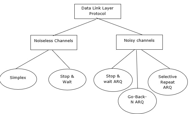
Data link layer protocols are divided into two categories based on whether the transmission channel is noiseless or noisy.
The data link layer protocol is diagrammatically represented below −
Noiseless Channels
There are two noiseless channels which are as follows −
- Simplex channel
- Stop & wait channel
Let us consider an ideal channel where no frames are lost, duplicated, or corrupted. We introduce two protocols for this type of channel. These two protocols are as follows −
- Protocol that does not use flow control.
- Protocol that uses the flow control.
Now let us consider the Protocols that do not use flow control −
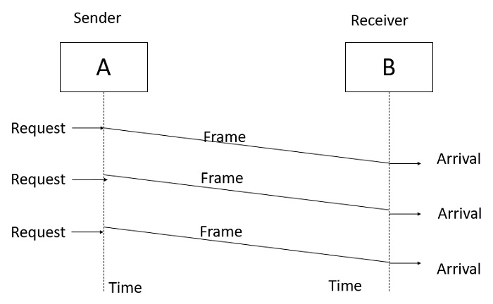
Simplest Protocol
Step 1 − Simplest protocol that does not have flow or error control.
Step 2 − It is a unidirectional protocol where data frames are traveling in one direction that is from the sender to receiver.
Step 3 − Let us assume that the receiver can handle any frame it receives with a processing time that is small enough to be negligible, the data link layer of the receiver immediately removes the header from the frame and hands the data packet to its network layer, which can also accept the packet immediately.
Stop-and-Wait Protocol
Step 1 − If the data frames that arrive at the receiver side are faster than they can be processed, the frames must be stored until their use.
Step 2 − Generally, the receiver does not have enough storage space, especially if it is receiving data from many sources. This may result in either discarding of frames or denial of service.
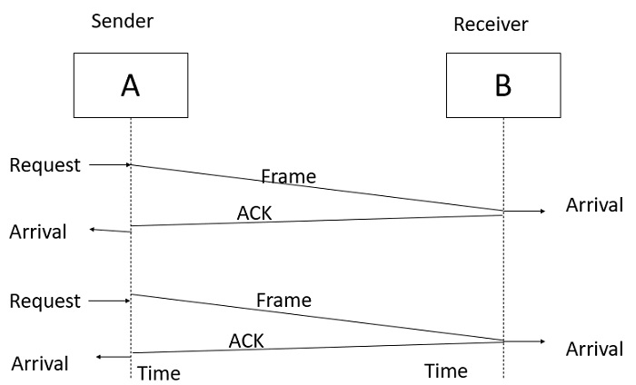
Step 3 − To prevent the receiver from becoming overwhelmed with frames, the sender must slow down. There must be ACK from the receiver to the sender.
Step 4 − In this protocol the sender sends one frame, stops until it receives confirmation from the receiver, and then sends the next frame.
Step 5 − We still have unidirectional communication for data frames, but auxiliary ACK frames travel from the other direction. We add flow control to the previous protocol.
Noisy Channels
There are three types of requests for the noisy channels, which are as follows −
- Stop & wait Automatic Repeat Request.
- Go-Back-N Automatic Repeat Request.
- Selective Repeat Automatic Repeat Request.
Noiseless channels are generally non-existent channels. We can ignore the error or we need to add error control to our protocols.
Stop and Wait Automatic Repeat Request
Step 1 − In a noisy channel, if a frame is damaged during transmission, the receiver will detect with the help of the checksum.
Step 2 − If a damaged frame is received, it will be discarded, and the transmitter will retransmit the same frame after receiving a proper acknowledgement.
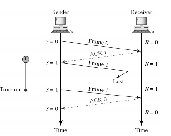
Step 3 − If the acknowledgement frame gets lost and the data link layer on 'A' eventually times out. Not having received an ACK, it assumes that its data frame was lost or damaged and sends the frame containing packet 1 again. This duplicate frame also arrives at the data link layer on 'B', thus part of the file will be duplicated and protocol is said to be failed.
Step 4 − To solve this problem, assign a sequence number in the header of the message.
Step 5 − The receiver checks the sequence number to determine if the message is a duplicate since only the message is transmitted at any time.
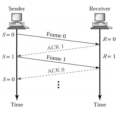
Step 6 − The sending and receiving station needs only a 1-bit alternating sequence of '0' or '1' to maintain the relationship of the transmitted message and its ACK/ NAK.
Step 7 − A modulo-2 numbering scheme is used where the frames are alternatively labelled with '0' or '1' and positive acknowledgements are of the form ACK 0 and ACK 1.
Normal operation of Stop & Wait ARQ is given below −
Stop & Wait ARQ with Lost frame is as follows −
Go-Back-N ARQ
To improve the transmission efficiency, we need more than one frame to be outstanding to keep the channel busy while the sender is waiting for acknowledgement.
There are two protocols developed for achieving this goal and they are as follows −
- Go – Back - N – Automatic – Repeat Request
- Sliding window protocol
Go-Back-N ARQ
Step 1 − In this protocol we can send several frames before receiving acknowledgements.
Step 2 − we keep a copy of these frames until the acknowledgment arrives.
Step 3 − Frames from a sending station are numbered sequentially. However, we need to include the sequence number of each frame in the header; we need to set a limit.
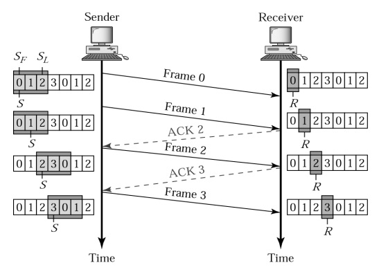
Step 4 − If the header of the frame allows m bits for the sequence number, the sequence numbers range from 0 to 2m-1. We can also repeat the sequence numbers.
Example
For m = 2, the range of sequence numbers is: 0 to 3, i.e.
0,1,2,3, 0,1,2,3,…
The Go-Back-N ARQ is shown below in diagram format −
Data Link Layer
- In the OSI model, the data link layer is a 4th layer from the top and 2nd layer from the bottom.
- The communication channel that connects the adjacent nodes is known as links, and in order to move the datagram from source to the destination, the datagram must be moved across an individual link.
- The main responsibility of the Data Link Layer is to transfer the datagram across an individual link.
- The Data link layer protocol defines the format of the packet exchanged across the nodes as well as the actions such as Error detection, retransmission, flow control, and random access.
- The Data Link Layer protocols are Ethernet, token ring, FDDI and PPP.
- An important characteristic of a Data Link Layer is that datagram can be handled by different link layer protocols on different links in a path. For example, the datagram is handled by Ethernet on the first link, PPP on the second link.
Following services are provided by the Data Link Layer:
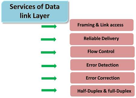
- Framing & Link access: Data Link Layer protocols encapsulate each network frame within a Link layer frame before the transmission across the link. A frame consists of a data field in which network layer datagram is inserted and a number of data fields. It specifies the structure of the frame as well as a channel access protocol by which frame is to be transmitted over the link.
- Reliable delivery: Data Link Layer provides a reliable delivery service, i.e., transmits the network layer datagram without any error. A reliable delivery service is accomplished with transmissions and acknowledgements. A data link layer mainly provides the reliable delivery service over the links as they have higher error rates and they can be corrected locally, link at which an error occurs rather than forcing to retransmit the data.
- Flow control: A receiving node can receive the frames at a faster rate than it can process the frame. Without flow control, the receiver's buffer can overflow, and frames can get lost. To overcome this problem, the data link layer uses the flow control to prevent the sending node on one side of the link from overwhelming the receiving node on another side of the link.
- Error detection: Errors can be introduced by signal attenuation and noise. Data Link Layer protocol provides a mechanism to detect one or more errors. This is achieved by adding error detection bits in the frame and then receiving node can perform an error check.
- Error correction: Error correction is similar to the Error detection, except that receiving node not only detect the errors but also determine where the errors have occurred in the frame.
- Half-Duplex & Full-Duplex: In a Full-Duplex mode, both the nodes can transmit the data at the same time. In a Half-Duplex mode, only one node can transmit the data at the same time.
The Medium Access Control Sublayer: The Channel Allocation Problem
When there are more than one user who desire to access a shared network channel, an algorithm is deployed for channel allocation among the competing users. The network channel may be a single cable or optical fiber connecting multiple nodes, or a portion of the wireless spectrum. Channel allocation algorithms allocate the wired channels and bandwidths to the users, who may be base stations, access points or terminal equipment.
Channel Allocation Schemes
Channel Allocation may be done using two schemes −
- Static Channel Allocation
- Dynamic Channel Allocation
Static Channel Allocation
In static channel allocation scheme, a fixed portion of the frequency channel is allotted to each user. For N competing users, the bandwidth is divided into N channels using frequency division multiplexing (FDM), and each portion is assigned to one user.
This scheme is also referred as fixed channel allocation or fixed channel assignment.
In this allocation scheme, there is no interference between the users since each user is assigned a fixed channel. However, it is not suitable in case of a large number of users with variable bandwidth requirements.
Dynamic Channel Allocation
In dynamic channel allocation scheme, frequency bands are not permanently assigned to the users. Instead channels are allotted to users dynamically as needed, from a central pool. The allocation is done considering a number of parameters so that transmission interference is minimized.
This allocation scheme optimises bandwidth usage and results is faster transmissions.
Dynamic channel allocation is further divided into centralised and distributed allocation.
Carrier Sense Multiple Access (CSMA)
This method was developed to decrease the chances of collisions when two or more stations start sending their signals over the data link layer. Carrier Sense multiple access requires that each station first check the state of the medium before sending.
Prerequisite - Multiple Access Protocols
Vulnerable Time:
Vulnerable time = Propagation time (Tp)
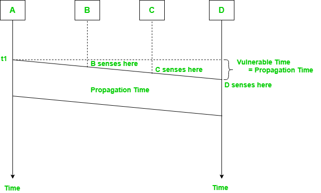
The persistence methods can be applied to help the station take action when the channel is busy/idle.
1. Carrier Sense Multiple Access with Collision Detection (CSMA/CD):
In this method, a station monitors the medium after it sends a frame to see if the transmission was successful. If successful, the transmission is finished, if not, the frame is sent again.
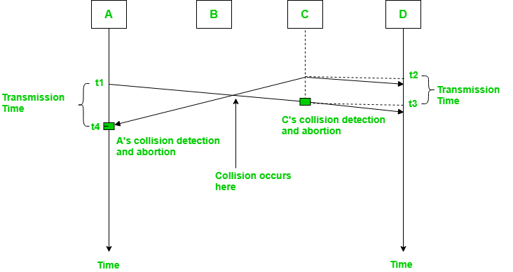
In the diagram, starts sending the first bit of its frame at t1 and since C sees the channel idle at t2, starts sending its frame at t2. C detects A’s frame at t3 and aborts transmission. A detects C’s frame at t4 and aborts its transmission. Transmission time for C’s frame is, therefore, t3-t2 and for A’s frame is t4-t1
So, the frame transmission time (Tfr) should be at least twice the maximum propagation time (Tp). This can be deduced when the two stations involved in a collision are a maximum distance apart.
Process: The entire process of collision detection can be explained as follows:
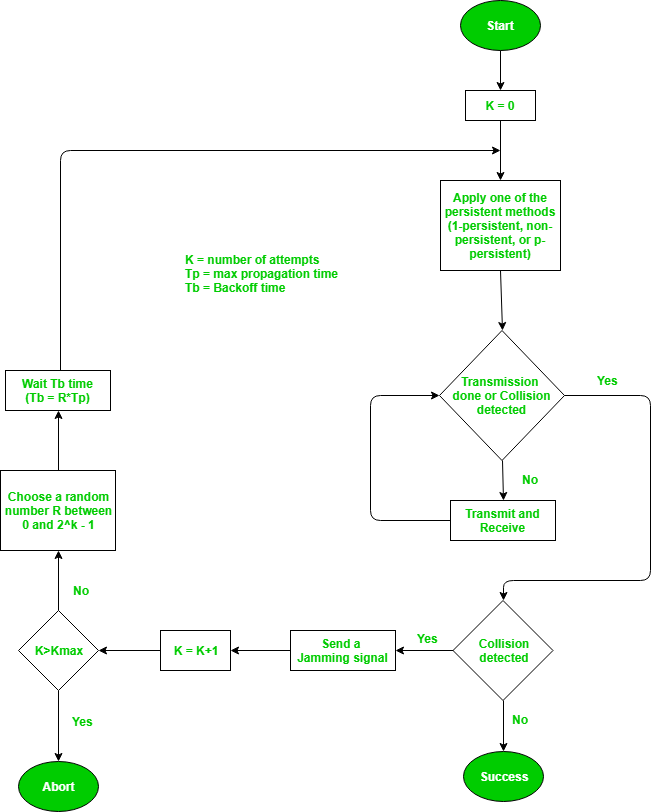
Throughput and Efficiency: The throughput of CSMA/CD is much greater than pure or slotted ALOHA.
- For the 1-persistent method, throughput is 50% when G=1.
- For the non-persistent method, throughput can go up to 90%.
2. Carrier Sense Multiple Access with Collision Avoidance (CSMA/CA) –
The basic idea behind CSMA/CA is that the station should be able to receive while transmitting to detect a collision from different stations. In wired networks, if a collision has occurred then the energy of the received signal almost doubles, and the station can sense the possibility of collision. In the case of wireless networks, most of the energy is used for transmission, and the energy of the received signal increases by only 5-10% if a collision occurs. It can’t be used by the station to sense collision. Therefore CSMA/CA has been specially designed for wireless networks.
These are three types of strategies:
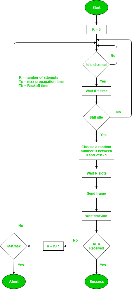
- InterFrame Space (IFS): When a station finds the channel busy it senses the channel again, when the station finds a channel to be idle it waits for a period of time called IFS time. IFS can also be used to define the priority of a station or a frame. Higher the IFS lower is the priority.
- Contention Window: It is the amount of time divided into slots. A station that is ready to send frames chooses a random number of slots as wait time.
- Acknowledgments: The positive acknowledgments and time-out timer can help guarantee a successful transmission of the frame.
Characteristics of CSMA/CA :
- Carrier Sense: The device listens to the channel before transmitting, to ensure that it is not currently in use by another device.
- Multiple Access: Multiple devices share the same channel and can transmit simultaneously.
- Collision Avoidance: If two or more devices attempt to transmit at the same time, a collision occurs. CSMA/CA uses random backoff time intervals to avoid collisions.
- Acknowledgment (ACK): After successful transmission, the receiving device sends an ACK to confirm receipt.
- Fairness: The protocol ensures that all devices have equal access to the channel and no single device monopolizes it.
- Binary Exponential Backoff: If a collision occurs, the device waits for a random period of time before attempting to retransmit. The backoff time increases exponentially with each retransmission attempt.
- Interframe Spacing: The protocol requires a minimum amount of time between transmissions to allow the channel to be clear and reduce the likelihood of collisions.
- RTS/CTS Handshake: In some implementations, a Request-To-Send (RTS) and Clear-To-Send (CTS) handshake is used to reserve the channel before transmission. This reduces the chance of collisions and increases efficiency.
- Wireless Network Quality: The performance of CSMA/CA is greatly influenced by the quality of the wireless network, such as the strength of the signal, interference, and network congestion.
- Adaptive Behavior: CSMA/CA can dynamically adjust its behavior in response to changes in network conditions, ensuring the efficient use of the channel and avoiding congestion.
Overall, CSMA/CA balances the need for efficient use of the shared channel with the need to avoid collisions, leading to reliable and fair communication in a wireless network.
Process: The entire process of collision avoidance can be explained as follows:
Types of CSMA Access Modes:
There are 4 types of access modes available in CSMA. It is also referred as 4 different types of CSMA protocols which decide the time to start sending data across shared media.
- 1-Persistent: It senses the shared channel first and delivers the data right away if the channel is idle. If not, it must wait and continuously track for the channel to become idle and then broadcast the frame without condition as soon as it does. It is an aggressive transmission algorithm.
- Non-Persistent: It first assesses the channel before transmitting data; if the channel is idle, the node transmits data right away. If not, the station must wait for an arbitrary amount of time (not continuously), and when it discovers the channel is empty, it sends the frames.
- P-Persistent: It consists of the 1-Persistent and Non-Persistent modes combined. Each node observes the channel in the P-Persistent mode, and if the channel is idle, it sends a frame with a P probability. If the data is not transferred, the frame restarts with the following time slot after waiting for a (q = 1-p probability) random period.
- O-Persistent: A supervisory node gives each node a transmission order. Nodes wait for their time slot according to their allocated transmission sequence when the transmission medium is idle.
Advantages of CSMA:
- Increased efficiency: CSMA ensures that only one device communicates on the network at a time, reducing collisions and improving network efficiency.
- Simplicity: CSMA is a simple protocol that is easy to implement and does not require complex hardware or software.
- Flexibility: CSMA is a flexible protocol that can be used in a wide range of network environments, including wired and wireless networks.
- Low cost: CSMA does not require expensive hardware or software, making it a cost-effective solution for network communication.
Disadvantages of CSMA:
- Limited scalability: CSMA is not a scalable protocol and can become inefficient as the number of devices on the network increases.
- Delay: In busy networks, the requirement to sense the medium and wait for an available channel can result in delays and increased latency.
- Limited reliability: CSMA can be affected by interference, noise, and other factors, resulting in unreliable communication.
- Vulnerability to attacks: CSMA can be vulnerable to certain types of attacks, such as jamming and denial-of-service attacks, which can disrupt network communication.
Introduction of Internetworking
Internetworking is combined of 2 words, inter and networking which implies an association between totally different nodes or segments. This connection area unit is established through intercessor devices akin to routers or gateway. The first term for associate degree internetwork was catenet. This interconnection is often among or between public, private, commercial, industrial, or governmental networks. Thus, associate degree internetwork could be an assortment of individual networks, connected by intermediate networking devices, that function as one giant network. Internetworking refers to the trade, products, and procedures that meet the challenge of making and administering internet works.
To enable communication, every individual network node or phase is designed with a similar protocol or communication logic, that is Transfer Control Protocol (TCP) or Internet Protocol (IP). Once a network communicates with another network having constant communication procedures, it’s called Internetworking. Internetworking was designed to resolve the matter of delivering a packet of information through many links.
There is a minute difference between extending the network and Internetworking. Merely exploitation of either a switch or a hub to attach 2 local area networks is an extension of LAN whereas connecting them via the router is an associate degree example of Internetworking. Internetworking is enforced in Layer three (Network Layer) of the OSI-ISO model. The foremost notable example of internetworking is the Internet.
There is chiefly 3 units of Internetworking:
- Extranet
- Intranet
- Internet
Intranets and extranets might or might not have connections to the net. If there is a connection to the net, the computer network or extranet area unit is usually shielded from being accessed from the net if it is not authorized. The net isn’t thought-about to be a section of the computer network or extranet, though it should function as a portal for access to parts of the associate degree extranet.
- Extranet – It’s a network of the internetwork that’s restricted in scope to one organization or entity however that additionally has restricted connections to the networks of one or a lot of different sometimes, however not essential. It’s the very lowest level of Internetworking, usually enforced in an exceedingly personal area. Associate degree extranet may additionally be classified as a Man, WAN, or different form of network however it cannot encompass one local area network i.e. it should have a minimum of one reference to associate degree external network.
- Intranet – This associate degree computer network could be a set of interconnected networks, which exploits the Internet Protocol and uses IP-based tools akin to web browsers and FTP tools, that are underneath the management of one body entity. That body entity closes the computer network to the remainder of the planet and permits solely specific users. Most typically, this network is the internal network of a corporation or different enterprise. An outsized computer network can usually have its own internet server to supply users with browsable data.
- Internet – A selected Internetworking, consisting of a worldwide interconnection of governmental, academic, public, and personal networks based mostly upon the Advanced analysis comes Agency Network (ARPANET) developed by ARPA of the U.S. Department of Defense additionally home to the World Wide Web (WWW) and cited as the ‘Internet’ to differentiate from all different generic Internetworks. Participants within the web, or their service suppliers, use IP Addresses obtained from address registries that manage assignments.
Internetworking has evolved as an answer to a few key problems: isolated LANs, duplication of resources, and an absence of network management. Isolated LANs created transmission problems between totally different offices or departments. Duplication of resources meant that constant hardware and code had to be provided to every workplace or department, as did a separate support employee. This lack of network management meant that no centralized methodology of managing and troubleshooting networks existed.
One more form of the interconnection of networks usually happens among enterprises at the Link Layer of the networking model, i.e. at the hardware-centric layer below the amount of the TCP/IP logical interfaces. Such interconnection is accomplished through network bridges and network switches. This can be typically incorrectly termed internetworking, however, the ensuing system is just a bigger, single subnetwork, and no internetworking protocol, akin to web Protocol, is needed to traverse these devices.
However, one electronic network is also reborn into associate degree internetwork by dividing the network into phases and logically dividing the segment traffic with routers. The Internet Protocol is meant to supply an associate degree unreliable packet service across the network. The design avoids intermediate network components maintaining any state of the network. Instead, this task is allotted to the endpoints of every communication session. To transfer information correctly, applications should utilize associate degree applicable Transport Layer protocol, akin to Transmission management Protocol (TCP), that provides a reliable stream. Some applications use a less complicated, connection-less transport protocol, User Datagram Protocol (UDP), for tasks that don’t need reliable delivery of information or that need period of time service, akin to video streaming or voice chat.
Internetwork Addressing –
Internetwork addresses establish devices severally or as members of a bunch. Addressing schemes differ based on the protocol family and therefore the OSI layer. Three kinds of internetwork addresses area units are ordinarily used: data-link layer addresses, Media Access control (MAC) addresses, and network-layer addresses.
- Data Link Layer addresses: A data-link layer address unambiguously identifies every physical network association of a network device. Data-link addresses typically area units cited as physical or hardware addresses. Data-link addresses sometimes exist among a flat address area and have a pre-established and usually fastened relationship to a selected device. End systems usually have just one physical network association, and therefore have just one data-link address. Routers and different internetworking devices usually have multiple physical network connections and so eventually have multiple data-link addresses.
- MAC Addresses: Media Access management (MAC) addresses encompass a set of data-link layer addresses. MAC addresses establish network entities in LANs that implement the IEEE MAC addresses of the data-link layer. MAC addresses different area units distinctively for every local area network interface. MAC addresses are forty-eight bits long and are expressed in form of twelve hexadecimal digits. The primary half dozen hexadecimal digits, which are usually administered by the IEEE, establish the manufacturer or merchant and therefore comprise the Organizational Unique Identifier (OUI). The last half dozen positional notation digits comprise the interface serial variety or another price administered by the particular merchant. MAC addresses are typically area units referred to as burned-in addresses (BIAs) as a result of being burned into read-only memory(ROM) and are traced into random-access memory (RAM) once the interface card initializes.
- Network-Layer Addresses: Network addresses sometimes exist among a gradable address area and typically area units referred to as virtual or logical addresses. the connection between a network address and a tool is logical and unfixed, it usually relies either on physical network characteristics or on groupings that don’t have any physical basis. finish systems need one network-layer address for every network-layer protocol they support. Routers and different Internetworking devices need one network-layer address per physical network association for every network-layer protocol supported.
Challenges to Internetworking –
Implementing useful internetwork isn’t at any certainty. There are several challenging fields, particularly in the areas of dependableness, connectivity, network management, and adaptability, and each and every space is essential in establishing associate degree economical and effective internetwork. A few of them are:-
- The initial challenge lies when we are trying to connect numerous systems to support communication between disparate technologies. For example, Totally different sites might use different kinds of media, or they could operate at variable speeds.
- Another essential thought is reliable service that should be maintained in an internetwork. Individual users and whole organizations depend upon consistent, reliable access to network resources.
- Network management should give centralized support associate degree troubleshooting capabilities on the internetwork. Configuration, security, performance, and different problems should be adequately addressed for the internetwork to perform swimmingly.
- Flexibility, the ultimate concern, is important for network enlargement and new applications and services, among different factors.
Advantages:
Increased connectivity: Internetworking enables devices on different networks to communicate with each other, which increases connectivity and enables new applications and services.
Resource sharing: Internetworking allows devices to share resources across networks, such as printers, servers, and storage devices. This can reduce costs and improve efficiency by allowing multiple devices to share resources.
Improved scalability: Internetworking allows networks to be expanded and scaled as needed to accommodate growing numbers of devices and users.
Improved collaboration: Internetworking enables teams and individuals to collaborate and work together more effectively, regardless of their physical location.
Access to remote resources: Internetworking allows users to access resources and services that are physically located on remote networks, improving accessibility and flexibility.
Disadvantages:
Security risks: Internetworking can create security vulnerabilities and increase the risk of cyberattacks and data breaches. Connecting multiple networks together increases the number of entry points for attackers, making it more difficult to secure the entire system.
Complexity: Internetworking can be complex and requires specialized knowledge and expertise to set up and maintain. This can increase costs and create additional maintenance overhead.
Performance issues: Internetworking can lead to performance issues, particularly if networks are not properly optimized and configured. This can result in slow response times and poor network performance.
Compatibility issues: Internetworking can lead to compatibility issues, particularly if different networks are using different protocols or technologies. This can make it difficult to integrate different systems and may require additional resources to resolve.
Management overhead: Internetworking can create additional management overhead, particularly if multiple networks are involved. This can increase costs and require additional resources to manage effectively.
IPv4 vs IPv6
What is IP?
An IP stands for internet protocol. An IP address is assigned to each device connected to a network. Each device uses an IP address for communication. It also behaves as an identifier as this address is used to identify the device on a network. It defines the technical format of the packets. Mainly, both the networks, i.e., IP and TCP, are combined together, so together, they are referred to as a TCP/IP. It creates a virtual connection between the source and the destination.
We can also define an IP address as a numeric address assigned to each device on a network. An IP address is assigned to each device so that the device on a network can be identified uniquely. To facilitate the routing of packets, TCP/IP protocol uses a 32-bit logical address known as IPv4(Internet Protocol version 4).
An IP address consists of two parts, i.e., the first one is a network address, and the other one is a host address.
There are two types of IP addresses:
- IPv4
- IPv6
What is IPv4?
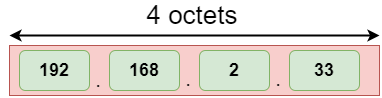
IPv4 is a version 4 of IP. It is a current version and the most commonly used IP address. It is a 32-bit address written in four numbers separated by 'dot', i.e., periods. This address is unique for each device.
For example, 66.94.29.13
The above example represents the IP address in which each group of numbers separated by periods is called an Octet. Each number in an octet is in the range from 0-255. This address can produce 4,294,967,296 possible unique addresses.
In today's computer network world, computers do not understand the IP addresses in the standard numeric format as the computers understand the numbers in binary form only. The binary number can be either 1 or 0. The IPv4 consists of four sets, and these sets represent the octet. The bits in each octet represent a number.
Each bit in an octet can be either 1 or 0. If the bit the 1, then the number it represents will count, and if the bit is 0, then the number it represents does not count.
Representation of 8 Bit Octet

The above representation shows the structure of 8- bit octet.
Now, we will see how to obtain the binary representation of the above IP address, i.e., 66.94.29.13
Step 1: First, we find the binary number of 66.

To obtain 66, we put 1 under 64 and 2 as the sum of 64 and 2 is equal to 66 (64+2=66), and the remaining bits will be zero, as shown above. Therefore, the binary bit version of 66 is 01000010.
Step 2: Now, we calculate the binary number of 94.

To obtain 94, we put 1 under 64, 16, 8, 4, and 2 as the sum of these numbers is equal to 94, and the remaining bits will be zero. Therefore, the binary bit version of 94 is 01011110.
Step 3: The next number is 29.

To obtain 29, we put 1 under 16, 8, 4, and 1 as the sum of these numbers is equal to 29, and the remaining bits will be zero. Therefore, the binary bit version of 29 is 00011101.
Step 4: The last number is 13.

To obtain 13, we put 1 under 8, 4, and 1 as the sum of these numbers is equal to 13, and the remaining bits will be zero. Therefore, the binary bit version of 13 is 00001101.
Drawback of IPv4
Currently, the population of the world is 7.6 billion. Every user is having more than one device connected with the internet, and private companies also rely on the internet. As we know that IPv4 produces 4 billion addresses, which are not enough for each device connected to the internet on a planet. Although the various techniques were invented, such as variable- length mask, network address translation, port address translation, classes, inter-domain translation, to conserve the bandwidth of IP address and slow down the depletion of an IP address. In these techniques, public IP is converted into a private IP due to which the user having public IP can also use the internet. But still, this was not so efficient, so it gave rise to the development of the next generation of IP addresses, i.e., IPv6.
What is IPv6?
IPv4 produces 4 billion addresses, and the developers think that these addresses are enough, but they were wrong. IPv6 is the next generation of IP addresses. The main difference between IPv4 and IPv6 is the address size of IP addresses. The IPv4 is a 32-bit address, whereas IPv6 is a 128-bit hexadecimal address. IPv6 provides a large address space, and it contains a simple header as compared to IPv4.
It provides transition strategies that convert IPv4 into IPv6, and these strategies are as follows:
- Dual stacking: It allows us to have both the versions, i.e., IPv4 and IPv6, on the same device.
- Tunneling: In this approach, all the users have IPv6 communicates with an IPv4 network to reach IPv6.
- Network Address Translation: The translation allows the communication between the hosts having a different version of IP.
This hexadecimal address contains both numbers and alphabets. Due to the usage of both the numbers and alphabets, IPv6 is capable of producing over 340 undecillion (3.4*1038) addresses.
IPv6 is a 128-bit hexadecimal address made up of 8 sets of 16 bits each, and these 8 sets are separated by a colon. In IPv6, each hexadecimal character represents 4 bits. So, we need to convert 4 bits to a hexadecimal number at a time
Address format
The address format of IPv4:
The address format of IPv6:

The above diagram shows the address format of IPv4 and IPv6. An IPv4 is a 32-bit decimal address. It contains 4 octets or fields separated by 'dot', and each field is 8-bit in size. The number that each field contains should be in the range of 0-255. Whereas an IPv6 is a 128-bit hexadecimal address. It contains 8 fields separated by a colon, and each field is 16-bit in size.
Differences between IPv4 and IPv6
| Ipv4 | Ipv6 | |
|---|---|---|
| Address length | IPv4 is a 32-bit address. | IPv6 is a 128-bit address. |
| Fields | IPv4 is a numeric address that consists of 4 fields which are separated by dot (.). | IPv6 is an alphanumeric address that consists of 8 fields, which are separated by colon. |
| Classes | IPv4 has 5 different classes of IP address that includes Class A, Class B, Class C, Class D, and Class E. | IPv6 does not contain classes of IP addresses. |
| Number of IP address | IPv4 has a limited number of IP addresses. | IPv6 has a large number of IP addresses. |
| VLSM | It supports VLSM (Virtual Length Subnet Mask). Here, VLSM means that Ipv4 converts IP addresses into a subnet of different sizes. | It does not support VLSM. |
| Address configuration | It supports manual and DHCP configuration. | It supports manual, DHCP, auto-configuration, and renumbering. |
| Address space | It generates 4 billion unique addresses | It generates 340 undecillion unique addresses. |
| End-to-end connection integrity | In IPv4, end-to-end connection integrity is unachievable. | In the case of IPv6, end-to-end connection integrity is achievable. |
| Security features | In IPv4, security depends on the application. This IP address is not developed in keeping the security feature in mind. | In IPv6, IPSEC is developed for security purposes. |
| Address representation | In IPv4, the IP address is represented in decimal. | In IPv6, the representation of the IP address in hexadecimal. |
| Fragmentation | Fragmentation is done by the senders and the forwarding routers. | Fragmentation is done by the senders only. |
| Packet flow identification | It does not provide any mechanism for packet flow identification. | It uses flow label field in the header for the packet flow identification. |
| Checksum field | The checksum field is available in IPv4. | The checksum field is not available in IPv6. |
| Transmission scheme | IPv4 is broadcasting. | On the other hand, IPv6 is multicasting, which provides efficient network operations. |
| Encryption and Authentication | It does not provide encryption and authentication. | It provides encryption and authentication. |
| Number of octets | It consists of 4 octets. | It consists of 8 fields, and each field contains 2 octets. Therefore, the total number of octets in IPv6 is 16. |
Ethernet is a set of technologies and protocols that are used primarily in LANs. It was first standardized in 1980s by IEEE 802.3 standard. IEEE 802.3 defines the physical layer and the medium access control (MAC) sub-layer of the data link layer for wired Ethernet networks. Ethernet is classified into two categories: classic Ethernet and switched Ethernet.
Classic Ethernet is the original form of Ethernet that provides data rates between 3 to 10 Mbps. The varieties are commonly referred as 10BASE-X. Here, 10 is the maximum throughput, i.e. 10 Mbps, BASE denoted use of baseband transmission, and X is the type of medium used. Most varieties of classic Ethernet have become obsolete in present communication scenario.
A switched Ethernet uses switches to connect to the stations in the LAN. It replaces the repeaters used in classic Ethernet and allows full bandwidth utilization.
IEEE 802.3 Popular Versions
There are a number of versions of IEEE 802.3 protocol. The most popular ones are -
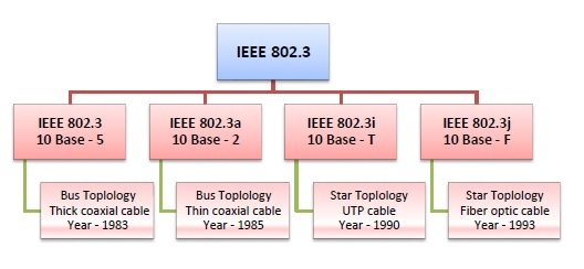
IEEE 802.3: This was the original standard given for 10BASE-5. It used a thick single coaxial cable into which a connection can be tapped by drilling into the cable to the core. Here, 10 is the maximum throughput, i.e. 10 Mbps, BASE denoted use of baseband transmission, and 5 refers to the maximum segment length of 500m.
IEEE 802.3a: This gave the standard for thin coax (10BASE-2), which is a thinner variety where the segments of coaxial cables are connected by BNC connectors. The 2 refers to the maximum segment length of about 200m (185m to be precise).
IEEE 802.3i: This gave the standard for twisted pair (10BASE-T) that uses unshielded twisted pair (UTP) copper wires as physical layer medium. The further variations were given by IEEE 802.3u for 100BASE-TX, 100BASE-T4 and 100BASE-FX.
IEEE 802.3i: This gave the standard for Ethernet over Fiber (10BASE-F) that uses fiber optic cables as medium of transmission.
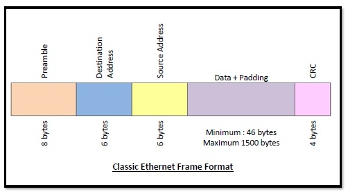
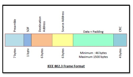
Frame Format of Classic Ethernet and IEEE 802.3
The main fields of a frame of classic Ethernet are -
Preamble: It is the starting field that provides alert and timing pulse for transmission. In case of classic Ethernet it is an 8 byte field and in case of IEEE 802.3 it is of 7 bytes.
Start of Frame Delimiter: It is a 1 byte field in a IEEE 802.3 frame that contains an alternating pattern of ones and zeros ending with two ones.
Destination Address: It is a 6 byte field containing physical address of destination stations.
Source Address: It is a 6 byte field containing the physical address of the sending station.
Length: It a 7 bytes field that stores the number of bytes in the data field.
Data: This is a variable sized field carries the data from the upper layers. The maximum size of data field is 1500 bytes.
Padding: This is added to the data to bring its length to the minimum requirement of 46 bytes.
CRC: CRC stands for cyclic redundancy check. It contains the error detection information.
Bluetooth is universal for short-range wireless voice and data communication. It is a Wireless Personal Area Network (WPAN) technology and is used for exchanging data over smaller distances. This technology was invented by Ericson in 1994. It operates in the unlicensed, industrial, scientific, and medical (ISM) band from 2.4 GHz to 2.485 GHz. Maximum devices that can be connected at the same time are 7. Bluetooth ranges up to 10 meters. It provides data rates up to 1 Mbps or 3 Mbps depending upon the version. The spreading technique that it uses is FHSS (Frequency-hopping spread spectrum). A Bluetooth network is called a piconet and a collection of interconnected piconets is called scatternet.
What is Bluetooth?
Bluetooth simply follows the principle of transmitting and receiving data using radio waves. It can be paired with the other device which has also Bluetooth but it should be within the estimated communication range to connect. When two devices start to share data, they form a network called piconet which can further accommodate more than five devices.
Points to remember for Bluetooth:
- Bluetooth Transmission capacity 720 kbps.
- Bluetooth is Wireless.
- Bluetooth is a Low-cost short-distance radio communications standard.
- Bluetooth is robust and flexible.
- Bluetooth is cable replacement technology that can be used to connect almost any device to any other device.
- The basic architecture unit of Bluetooth is a piconet.
Bluetooth Architecture:
The architecture of Bluetooth defines two types of networks:
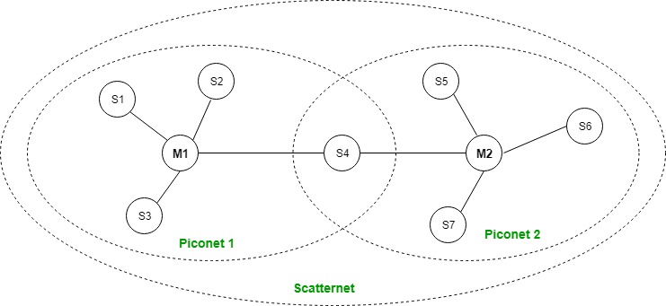
1. Piconet
2. Scatternet
Piconet:
Piconet is a type of Bluetooth network that contains one primary node called the master node and seven active secondary nodes called slave nodes. Thus, we can say that there is a total of 8 active nodes which are present at a distance of 10 meters. The communication between the primary and secondary nodes can be one-to-one or one-to-many. Possible communication is only between the master and slave; Slave-slave communication is not possible. It also has 255 parked nodes, these are secondary nodes and cannot take participation in communication unless it gets converted to the active state.
Scatternet:
It is formed by using various piconets. A slave that is present in one piconet can act as master or we can say primary in another piconet. This kind of node can receive a message from a master in one piconet and deliver the message to its slave in the other piconet where it is acting as a master. This type of node is referred to as a bridge node. A station cannot be mastered in two piconets.
Bluetooth protocol stack:
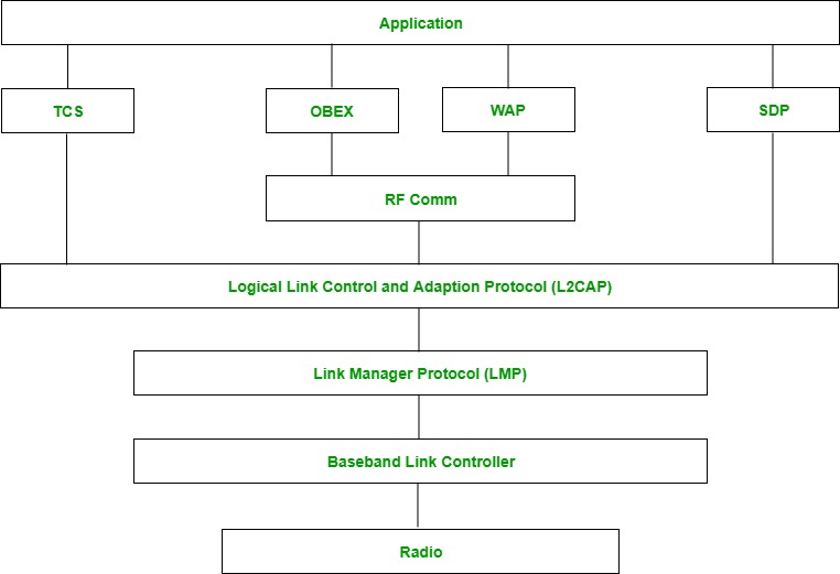
- Radio (RF) layer: It specifies the details of the air interface, including frequency, the use of frequency hopping and transmit power. It performs modulation/demodulation of the data into RF signals. It defines the physical characteristics of Bluetooth transceivers. It defines two types of physical links: connection-less and connection-oriented.
- Baseband Link layer: The baseband is the digital engine of a Bluetooth system and is equivalent to the MAC sublayer in LANs. It performs the connection establishment within a piconet, addressing, packet format, timing and power control.
- Link Manager protocol layer: It performs the management of the already established links which includes authentication and encryption processes. It is responsible for creating the links, monitoring their health, and terminating them gracefully upon command or failure.
- Logical Link Control and Adaption (L2CAP) Protocol layer: It is also known as the heart of the Bluetooth protocol stack. It allows the communication between upper and lower layers of the Bluetooth protocol stack. It packages the data packets received from upper layers into the form expected by lower layers. It also performs segmentation and multiplexing.
- Service Discovery Protocol (SDP) layer: It is short for Service Discovery Protocol. It allows discovering the services available on another Bluetooth-enabled device.
- RF comm layer: It is a cabal replacement protocol. It is short for Radio Frontend Component. It provides a serial interface with WAP and OBEX. It also provides emulation of serial ports over the logical link control and adaption protocol(L2CAP). The protocol is based on the ETSI standard TS 07.10.
- OBEX: It is short for Object Exchange. It is a communication protocol to exchange objects between 2 devices.
- WAP: It is short for Wireless Access Protocol. It is used for internet access.
- TCS: It is short for Telephony Control Protocol. It provides telephony service. The basic function of this layer is call control (setup & release) and group management for the gateway serving multiple devices.
- Application layer: It enables the user to interact with the application.
Types of Bluetooth
Various types of Bluetooth are available in the market nowadays. Let us look at them.
- In-Car Headset: One can make calls from the car speaker system without the use of mobile phones.
- Stereo Headset: To listen to music in car or in music players at home.
- Webcam: One can link the camera with the help of Bluetooth with their laptop or phone.
- Bluetooth-equipped Printer: The printer can be used when connected via Bluetooth with mobile phone or laptop.
- Bluetooth Global Positioning System (GPS): To use GPS in cars, one can connect their phone with car system via Bluetooth to fetch the directions of the address.
Advantage:
- It is a low-cost and easy-to-use device.
- It can also penetrate through walls.
- It creates an Ad-hoc connection immediately without any wires.
- It is used for voice and data transfer.
Disadvantages:
- It can be hacked and hence, less secure.
- It has a slow data transfer rate: of 3 Mbps.
- It has a small range: 10 meters.
- Bluetooth communication does not support routing.
- The issues of handoffs have not been addressed.
Applications:
- It can be used in laptops, and in wireless PCs, printers.
- It can be used in wireless headsets, wireless PANs, and LANs.
- It can connect a digital camera wirelessly to a mobile phone.
- It can transfer data in terms of videos, songs, photographs, or files from one cell phone to another cell phone or computer.
- It is used in the sectors of Medical health care, sports and fitness, Military.
Design Issues in Network Layer
Network layer is majorly focused on getting packets from the source to the destination, routing error handling and congestion control.
Before learning about design issues in the network layer, let’s learn about it’s various functions.
- Addressing:
Maintains the address at the frame header of both source and destination and performs addressing to detect various devices in network. - Packeting:
This is performed by Internet Protocol. The network layer converts the packets from its upper layer. - Routing:
It is the most important functionality. The network layer chooses the most relevant and best path for the data transmission from source to destination. - Inter-networking:
It works to deliver a logical connection across multiple devices.
Network layer design issues:
The network layer comes with some design issues they are described as follows:
1. Store and Forward packet switching:
The host sends the packet to the nearest router. This packet is stored there until it has fully arrived once the link is fully processed by verifying the checksum then it is forwarded to the next router till it reaches the destination. This mechanism is called “Store and Forward packet switching.”
2. Services provided to Transport Layer:
Through the network/transport layer interface, the network layer transfers it’s services to the transport layer. These services are described below.
But before providing these services to the transfer layer following goals must be kept in mind :-
- Offering services must not depend on router technology.
- The transport layer needs to be protected from the type, number and topology of the available router.
- The network addresses for the transport layer should use uniform numbering pattern also at LAN and WAN connections.
Based on the connections there are 2 types of services provided :
- Connectionless – The routing and insertion of packets into subnet is done individually. No added setup is required.
- Connection-Oriented – Subnet must offer reliable service and all the packets must be transmitted over a single route.
3. Implementation of Connectionless Service:
Packet are termed as “datagrams” and corresponding subnet as “datagram subnets”. When the message size that has to be transmitted is 4 times the size of the packet, then the network layer divides into 4 packets and transmits each packet to router via. a few protocol.Each data packet has destination address and is routed independently irrespective of the packets.
4. Implementation of Connection Oriented service:
To use a connection-oriented service, first we establishes a connection, use it and then release it. In connection-oriented services, the data packets are delivered to the receiver in the same order in which they have been sent by the sender.
It can be done in either two ways :
- Circuit Switched Connection – A dedicated physical path or a circuit is established between the communicating nodes and then data stream is transferred.
- Virtual Circuit Switched Connection – The data stream is transferred over a packet switched network, in such a way that it seems to the user that there is a dedicated path from the sender to the receiver. A virtual path is established here. While, other connections may also be using the same path.
Differences between Virtual Circuits and Datagram Networks
Both Virtual Circuits and Datagram Networks are the types of connection services which are used for transmission of information from a sender to a receiver. The most basic difference between the two is that the virtual circuits are connectionoriented services that require resources like buffers, CPU, bandwidth, etc., for a data transfer session, while the datagram networks are connectionless services where no such resources are required for data transmission.
There are many other key differences between virtual circuits and datagram networks, which we will discuss in this article.
What are Virtual Circuits?
Virtual Circuit is a connectionoriented service in which resources like buffers, CPU, bandwidth, etc. are used for creating a data transfer session. Virtual Circuit is also known as connection-oriented switching.
In virtual circuits, the path that is followed by the first data packet would get fixed and all other data packets will also use the same path and consume the same resources. Consequently, a common and same header is used by all the data packets.
Due to all these reasons, virtual circuits are comparatively less complex and more reliable for data transmission, however they are expensive to install and maintain. Virtual circuits are mostly used in Asynchronous Transfer Mode (ATM) Networks that are used for the telephone calls.
What are Datagram Networks?
Datagram networks are connectionless services for data transmission, in which no resources like CPU, buffer, bandwidth, etc. are required for data transmission. In datagram networks, the path for data transmission is not fixed. Therefore, the data packets are free to decide the path on any intermediate router on the way by dynamically changing the routing tables on the routers.
Since the data packets follow different paths, they have different headers with information of the data packets. Due to dynamic resource allocation and dynamic path, datagram networks are errorprone and less reliable. However, datagram networks are cheaper to install and maintain. They are widely used in IP (Internet Protocol) services like internet.
Difference between Virtual Circuits and Datagram Networks
The following are the important differences between Virtual Circuits and Datagram Networks −
Key | Virtual Circuits | Datagram Networks |
|---|---|---|
Definition | Virtual Circuit is a connection-oriented service in which there is an implementation of resources like buffers, CPU, bandwidth, etc., used by virtual circuit for a data transfer session. | Datagram networks are a type of connectionless service where no such resources are required for data transmission. |
Path | In Virtual circuits, as all the resources and bandwidth get reserved before the transmission, the path which is utilized or followed by first data packet would get fixed and all other data packets will use the same path and consume same resources. | In a Datagram network, the path is not fixed as data packets are free to decide the path on any intermediate router on the go by dynamically changing routing tables on routers. |
Header | As there is same path followed by all the data packets, a common and same header is being used by all the packets. | Different headers with information of other data packet is being used in Datagram network. |
Complexity | Virtual Circuit is less complex as compared to that of Datagram network. | Datagram network are more complex as compared to Virtual circuit. |
Reliability | Due to fixed path and assurance of fixed resources, Virtual Circuits are more reliable for data transmission as compared to Datagram network. | Datagram networks, due to their dynamic resource allocation and dynamic path, are more errorprone and less reliable than Virtual circuits. |
Example and Cost | Virtual circuits are costlier in installation and maintenance. They are widely used by ATM (Asynchronous Transfer Mode) Network, which is used for the Telephone calls. | Datagram networks are cheaper as compared to the Virtual Circuits. They are mainly used by IP network, which is used for Data services like Internet. |
Conclusion
The most significant difference between the two is that, in case of virtual circuits, the path which is followed by the first data packet would get fixed and all other data packets will also use the same path; whereas in datagram networks, the path is not fixed, thus the data packets are free to decide the path on any intermediate router on the go by dynamically changing the routing tables on the routers.
Multicasting in Computer Network
Multicast is a method of group communication where the sender sends data to multiple receivers or nodes present in the network simultaneously. Multicasting is a type of one-to-many and many-to-many communication as it allows sender or senders to send data packets to multiple receivers at once across LANs or WANs. This process helps in minimizing the data frame of the network.
Multicasting works in similar to Broadcasting, but in Multicasting, the information is sent to the targeted or specific members of the network. This task can be accomplished by transmitting individual copies to each user or node present in the network, but sending individual copies to each user is inefficient and might increase the network latency. To overcome these shortcomings, multicasting allows a single transmission that can be split up among the multiple users, consequently, this reduces the bandwidth of the signal.
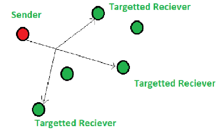
Applications :
Multicasting is used in many areas like:
- Internet protocol (IP)
- Streaming Media
It also supports video conferencing applications and webcasts.
IP Multicast :
Multicasting that takes place over the Internet is known as IP Multicasting. These multicast follow the internet protocol(IP) to transmit data. IP multicasting uses a mechanism known as ‘Multicast trees’ to transmit to information among the users of the network. Multicast trees; allows a single transmission to branch out to the desired receivers. The branches are created at the Internet routers, the branches are created such that the length of the transmission will be minimum.
IP multicasts also use two other essential protocols to function; Internet Group Management Protocol (IGMP), Protocol Independent Multicast (PIM). IGMP allows the recipients to access the data or information. The network routers use PIM to create multicast trees.
To sum up, Multicasting is an efficient way of communication; it reduces the bandwidth usage.
MANET Routing Protocols
In Mobile Ad hoc Network (MANET), nodes do not know the topology of their network, instead they have to discover it by their own as the topology in the ad-hoc network is dynamic topology. The basic rules is that a new node whenever enters into an ad-hoc network, must announce its arrival and presence and should also listen to similar announcement broadcasts made by other mobile nodes.

1. Pro-active routing protocols: These are also known as table-driven routing protocols. Each mobile node maintains a separate routing table which contains the information of the routes to all the possible destination mobile nodes.
Since the topology in the mobile ad-hoc network is dynamic, these routing tables are updated periodically as and when the network topology changes. It has a limitation that it doesn’t work well for the large networks as the entries in the routing table becomes too large since they need to maintain the route information to all possible nodes.
- Destination Sequenced Distance Vector Routing Protocol (DSDV): It is a pro-active/table driven routing protocol. It actually extends the distance vector routing protocol of the wired networks as the name suggests. It is based on the Bellman-ford routing algorithm. Distance vector routing protocol was not suited for mobile ad-hoc networks due to count-to-infinity problem. Hence, as a solution Destination Sequenced Distance Vector Routing Protocol (DSDV) came into picture.
Destination sequence number is added with every routing entry in the routing table maintained by each node. A node will include the new update in the table only if the entry consists of the new updated route to the destination with higher sequence number. - Global State Routing (GSR): It is a pro-active/table driven routing protocol. It actually extends the link state routing of the wired networks. It is based on the Dijkstra’s routing algorithm. Link state routing protocol was not suited for mobile ad-hoc networks because in it, each node floods the link state routing information directly into the whole network i.e. Global flooding which may lead to the congestion of control packets in the network.
Hence, as a solution Global State Routing Protocol (GSR) came into the picture. Global state routing doesn’t flood the link state routing packets globally into the network. In GSR, each of the mobile node maintains one list and three tables namely, adjacency list, topology table, next hop table and distance table.
2. Reactive routing protocols: These are also known as on-demand routing protocol. In this type of routing, the route is discovered only when it is required/needed. The process of route discovery occurs by flooding the route request packets throughout the mobile network. It consists of two major phases namely, route discovery and route maintenance.
- Dynamic Source Routing protocol (DSR): It is a reactive/on-demand routing protocol. In this type of routing, the route is discovered only when it is required/needed. The process of route discovery occurs by flooding the route request packets throughout the mobile network. It consists of two phases:
- Route Discovery: This phase determines the most optimal path for the transmission of data packets between the source and the destination mobile nodes.
- Route Maintenance: This phase performs the maintenance work of the route as the topology in the mobile ad-hoc network is dynamic in nature and hence, there are many cases of link breakage resulting in the network failure between the mobile nodes.
- Ad-Hoc On Demand Vector Routing protocol (AODV): It is a reactive/on-demand routing protocol. It is an extension of dynamic source routing protocol (DSR) and it helps to remove the disadvantage of dynamic source routing protocol. In DSR, after route discovery, when the source mobile node sends the data packet to the destination mobile node, it also contains the complete path in its header. Hence, as the network size increases, the length of the complete path also increases and the data packet’s header size also increases which makes the whole network slow.
Hence, Ad-Hoc On Demand Vector Routing protocol came as solution to it. The main difference lies in the way of storing the path, AODV stores the path in the routing table whereas DSR stores it in the data packet’s header itself. It also operates in two phases in the similar fashion: Route discovery and Route maintenance.
3. Hybrid Routing protocol: It basically combines the advantages of both, reactive and pro-active routing protocols. These protocols are adaptive in nature and adapts according to the zone and position of the source and destination mobile nodes. One of the most popular hybrid routing protocol is Zone Routing Protocol (ZRP).
The whole network is divided into different zones and then the position of source and destination mobile node is observed. If the source and destination mobile nodes are present in the same zone, then proactive routing is used for the transmission of the data packets between them. And if the source and destination mobile nodes are present in different zones, then reactive routing is used for the transmission of the data packets between them.

Characteristics of MANET Routing Protocol:
To avoid the problems with routing in MANET, routing protocols should have following characteristics:
- It should be widely distributed.
- It must be localized.
- Because of nodes mobility, it should be adjustable to frequent change in topology.
- It must be free of impermeable routes.
- The convergence of routes must be fast.
- Each node in the network should be required to store information about the network’s stable local topology.
- It should be able to provide high-quality service.
- As delay increases, performance decreases.
- If delay increases, retransmission occurs, making situation worse.
- Congestion Control is a mechanism that controls the entry of data packets into the network, enabling a better use of a shared network infrastructure and avoiding congestive collapse.
- Congestive-Avoidance Algorithms (CAA) are implemented at the TCP layer as the mechanism to avoid congestive collapse in a network.
- There are two congestion control algorithm which are as follows:
- Leaky Bucket Algorithm
- The leaky bucket algorithm discovers its use in the context of network traffic shaping or rate-limiting.
- A leaky bucket execution and a token bucket execution are predominantly used for traffic shaping algorithms.
- This algorithm is used to control the rate at which traffic is sent to the network and shape the burst traffic to a steady traffic stream.
- The disadvantages compared with the leaky-bucket algorithm are the inefficient use of available network resources.
- The large area of network resources such as bandwidth is not being used effectively.
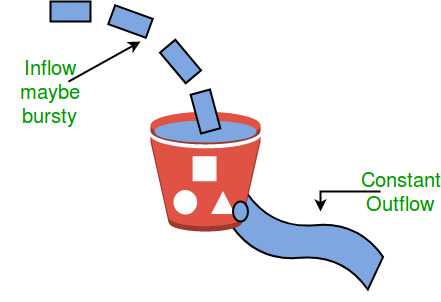
- When host wants to send packet, packet is thrown into the bucket.
- The bucket leaks at a constant rate, meaning the network interface transmits packets at a constant rate.
- Bursty traffic is converted to a uniform traffic by the leaky bucket.
- In practice the bucket is a finite queue that outputs at a finite rate.
- Token bucket Algorithm
- The leaky bucket algorithm has a rigid output design at an average rate independent of the bursty traffic.
- In some applications, when large bursts arrive, the output is allowed to speed up. This calls for a more flexible algorithm, preferably one that never loses information. Therefore, a token bucket algorithm finds its uses in network traffic shaping or rate-limiting.
- It is a control algorithm that indicates when traffic should be sent. This order comes based on the display of tokens in the bucket.
- The bucket contains tokens. Each of the tokens defines a packet of predetermined size. Tokens in the bucket are deleted for the ability to share a packet.
- When tokens are shown, a flow to transmit traffic appears in the display of tokens.
- No token means no flow sends its packets. Hence, a flow transfers traffic up to its peak burst rate in good tokens in the bucket.
- In regular intervals tokens are thrown into the bucket. ƒ
- The bucket has a maximum capacity. ƒ
- If there is a ready packet, a token is removed from the bucket, and the packet is sent.
- If there is no token in the bucket, the packet cannot be sent.
Ways in which token bucket is superior to leaky bucket: The leaky bucket algorithm controls the rate at which the packets are introduced in the network, but it is very conservative in nature. Some flexibility is introduced in the token bucket algorithm. In the token bucket, algorithm tokens are generated at each tick (up to a certain limit). For an incoming packet to be transmitted, it must capture a token and the transmission takes place at the same rate. Hence some of the busty packets are transmitted at the same rate if tokens are available and thus introduces some amount of flexibility in the system.
Formula: M * s = C + ρ * s where S – is time taken M – Maximum output rate ρ – Token arrival rate C – Capacity of the token bucket in byte
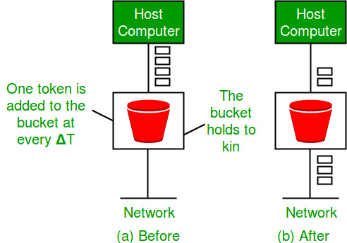
This article is contributed by Vikash Kumar. Please write comments if you find anything incorrect, or you want to share more information about the topic discussed above
What are the elements of Transport Protocol
To establish a reliable service between two machines on a network, transport protocols are implemented, which somehow resembles the data link protocols implemented at layer 2. The major difference lies in the fact that the data link layer uses a physical channel between two routers while the transport layer uses a subnet.
Following are the issues for implementing transport protocols−
Types of Service
The transport layer also determines the type of service provided to the users from the session layer. An error-free point-to-point communication to deliver messages in the order in which they were transmitted is one of the key functions of the transport layer.
Error Control
Error detection and error recovery are an integral part of reliable service, and therefore they are necessary to perform error control mechanisms on an end-to-end basis. To control errors from lost or duplicate segments, the transport layer enables unique segment sequence numbers to the different packets of the message, creating virtual circuits, allowing only one virtual circuit per session.
Flow Control
The underlying rule of flow control is to maintain a synergy between a fast process and a slow process. The transport layer enables a fast process to keep pace with a slow one. Acknowledgements are sent back to manage end-to-end flow control. Go back N algorithms are used to request retransmission of packets starting with packet number N. Selective Repeat is used to request specific packets to be retransmitted.
Connection Establishment/Release
The transport layer creates and releases the connection across the network. This includes a naming mechanism so that a process on one machine can indicate with whom it wishes to communicate. The transport layer enables us to establish and delete connections across the network to multiplex several message streams onto one communication channel.
Multiplexing/De multiplexing
The transport layer establishes a separate network connection for each transport connection required by the session layer. To improve throughput, the transport layer establishes multiple network connections. When the issue of throughput is not important, it multiplexes several transport connections onto the same network connection, thus reducing the cost of establishing and maintaining the network connections.
When several connections are multiplexed, they call for demultiplexing at the receiving end. In the case of the transport layer, the communication takes place only between two processes and not between two machines. Hence, communication at the transport layer is also known as peer-to-peer or process-to-process communication.
Fragmentation and re-assembly
When the transport layer receives a large message from the session layer, it breaks the message into smaller units depending upon the requirement. This process is called fragmentation. Thereafter, it is passed to the network layer. Conversely, when the transport layer acts as the receiving process, it reorders the pieces of a message before reassembling them into a message.
Addressing
Transport Layer deals with addressing or labelling a frame. It also differentiates between a connection and a transaction. Connection identifiers are ports or sockets that label each frame, so the receiving device knows which process it has been sent from. This helps in keeping track of multiple-message conversations. Ports or sockets address multiple conservations in the same location.
TCP Connection Establishment
TCP is a connection-oriented protocol and every connection-oriented protocol needs to establish a connection in order to reserve resources at both the communicating ends.
Connection Establishment –
1. Sender starts the process with the following:
- Sequence number (Seq=521): contains the random initial sequence number generated at the sender side.
- Syn flag (Syn=1): request the receiver to synchronize its sequence number with the above-provided sequence number.
- Maximum segment size (MSS=1460 B): sender tells its maximum segment size, so that receiver sends datagram which won’t require any fragmentation. MSS field is present inside Option field in TCP header.
- Window size (window=14600 B): sender tells about his buffer capacity in which he has to store messages from the receiver.
2. TCP is a full-duplex protocol so both sender and receiver require a window for receiving messages from one another.
- Sequence number (Seq=2000): contains the random initial sequence number generated at the receiver side.
- Syn flag (Syn=1): request the sender to synchronize its sequence number with the above-provided sequence number.
- Maximum segment size (MSS=500 B): receiver tells its maximum segment size, so that sender sends datagram which won’t require any fragmentation. MSS field is present inside Option field in TCP header.
Since MSSreceiver < MSSsender, both parties agree for minimum MSS i.e., 500 B to avoid fragmentation of packets at both ends.
Therefore, receiver can send maximum of 14600/500 = 29 packets.
This is the receiver's sending window size.
- Window size (window=10000 B): receiver tells about his buffer capacity in which he has to store messages from the sender.
Therefore, sender can send a maximum of 10000/500 = 20 packets.
This is the sender's sending window size.
- Acknowledgement Number (Ack no.=522): Since sequence number 521 is received by the receiver so, it makes a request for the next sequence number with Ack no.=522 which is the next packet expected by the receiver since Syn flag consumes 1 sequence no.
- ACK flag (ACk=1): tells that the acknowledgement number field contains the next sequence expected by the receiver.
3. Sender makes the final reply for connection establishment in the following way:
- Sequence number (Seq=522): since sequence number = 521 in 1st step and SYN flag consumes one sequence number hence, the next sequence number will be 522.
- Acknowledgement Number (Ack no.=2001): since the sender is acknowledging SYN=1 packet from the receiver with sequence number 2000 so, the next sequence number expected is 2001.
- ACK flag (ACK=1): tells that the acknowledgement number field contains the next sequence expected by the sender.

Since the connection establishment phase of TCP makes use of 3 packets, it is also known as 3-way Handshaking (SYN, SYN + ACK, ACK).
TCP vs UDP
What is the TCP?
The TCP stands for Transmission Control Protocol. If we want the communication between two computers and communication should be good and reliable. For example, we want to view a web page, then we expect that nothing should be missing on the page, or we want to download a file, then we require a complete file, i.e., nothing should be missing either it could be a text or an image. This can only be possible due to the TCP. It is one of the most widely used protocols over the TCP/IP network.
Features of TCP
The following are the features of the TCP:
- Data delivery
TCP protocol ensures that the data is received correctly, no data is missing and in order. If TCP protocol is not used, then the incorrect data can be received or out of order. For example, if we try to view the web page or download a file without using TCP, then some data or images could be missing. - Protocol
TCP is a connection-oriented protocol. Through the word connection-oriented, we understand that the computers first establish a connection and then do the communication. This is done by using a three-way handshake. In a three-way handshake, the first sender sends the SYN message to the receiver then the receiver sends back the SYN ACK message to confirm that the message has been received. After receiving the SYN ACK message, the sender sends the acknowledgment message to the receiver. In this way, the connection is established between the computers. Once the connection is established, the data will be delivered. This protocol guarantees the data delivery means that if the data is not received then the TCP will resend the data.
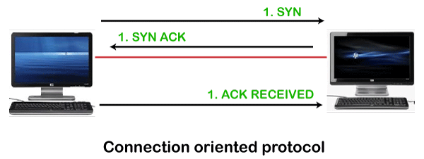
What is UDP?
The UDP stands for User Datagram Protocol. Its working is similar to the TCP as it is also used for sending and receiving the message. The main difference is that UDP is a connectionless protocol. Here, connectionless means that no connection establishes prior to communication. It also does not guarantee the delivery of data packets. It does not even care whether the data has been received on the receiver's end or not, so it is also known as the "fire-and-forget" protocol. It is also known as the "fire-and-forget" protocol as it sends the data and does not care whether the data is received or not. UDP is faster than TCP as it does not provide the assurance for the delivery of the packets.
Differences between the TCP and UDP
- Type of protocol
Both the protocols, i.e., TCP and UDP, are the transport layer protocol. TCP is a connection-oriented protocol, whereas UDP is a connectionless protocol. It means that TCP requires connection prior to the communication, but the UDP does not require any connection. - Reliability
TCP is a reliable protocol as it provides assurance for the delivery of the data. It follows the acknowledgment mechanism. In this mechanism, the sender receives the acknowledgment from the receiver and checks whether the acknowledgment is positive or negative. If the ACK is positive means, the data has been received successfully. If ACK is negative, then TCP will resend the data. It also follows the flow and error control mechanism.
UDP is an unreliable protocol as it does not ensure the delivery of the data. - Flow Control
TCP follows the flow control mechanism that ensures a large number of packets are not sent to the receiver at the same time, while UDP does not follow the flow control mechanism. - Ordering
TCP uses ordering and sequencing techniques to ensure that the data packets are received in the same order in which they are sent. On the other hand, UDP does not follow any ordering and sequencing technique; i.e., data can be sent in any sequence. - Speed
Since TCP establishes a connection between a sender and receiver, performs error checking, and also guarantees the delivery of data packets while UDP neither creates a connection nor it guarantees the delivery of data packets, so UDP is faster than TCP. - Flow of data
In TCP, data can flow in both directions means that it provides the full-duplex service. On the other hand, UDP is mainly suitable for the unidirectional flow of data.
Let's look at the differences between the TCP and UDP in a tabular form.
| TCP | UDP | |
|---|---|---|
| Full form | It stands for Transmission Control Protocol. | It stands for User Datagram Protocol. |
| Type of connection | It is a connection-oriented protocol, which means that the connection needs to be established before the data is transmitted over the network. | It is a connectionless protocol, which means that it sends the data without checking whether the system is ready to receive or not. |
| Reliable | TCP is a reliable protocol as it provides assurance for the delivery of data packets. | UDP is an unreliable protocol as it does not take the guarantee for the delivery of packets. |
| Speed | TCP is slower than UDP as it performs error checking, flow control, and provides assurance for the delivery of | UDP is faster than TCP as it does not guarantee the delivery of data packets. |
| Header size | The size of TCP is 20 bytes. | The size of the UDP is 8 bytes. |
| Acknowledgment | TCP uses the three-way-handshake concept. In this concept, if the sender receives the ACK, then the sender will send the data. TCP also has the ability to resend the lost data. | UDP does not wait for any acknowledgment; it just sends the data. |
| Flow control mechanism | It follows the flow control mechanism in which too many packets cannot be sent to the receiver at the same time. | This protocol follows no such mechanism. |
| Error checking | TCP performs error checking by using a checksum. When the data is corrected, then the data is retransmitted to the receiver. | It does not perform any error checking, and also does not resend the lost data packets. |
| Applications | This protocol is mainly used where a secure and reliable communication process is required, like military services, web browsing, and e-mail. | This protocol is used where fast communication is required and does not care about the reliability like VoIP, game streaming, video and music streaming, etc. |
What is DNS?
The Domain Name System (DNS) is the phonebook of the Internet. Humans access information online through domain names, like nytimes.com or espn.com. Web browsers interact through Internet Protocol (IP) addresses. DNS translates domain names to IP addresses so browsers can load Internet resources.
Each device connected to the Internet has a unique IP address which other machines use to find the device. DNS servers eliminate the need for humans to memorize IP addresses such as 192.168.1.1 (in IPv4), or more complex newer alphanumeric IP addresses such as 2400:cb00:2048:1::c629:d7a2 (in IPv6).
How does DNS work?
The process of DNS resolution involves converting a hostname (such as www.example.com) into a computer-friendly IP address (such as 192.168.1.1). An IP address is given to each device on the Internet, and that address is necessary to find the appropriate Internet device - like a street address is used to find a particular home. When a user wants to load a webpage, a translation must occur between what a user types into their web browser (example.com) and the machine-friendly address necessary to locate the example.com webpage.
In order to understand the process behind the DNS resolution, it’s important to learn about the different hardware components a DNS query must pass between. For the web browser, the DNS lookup occurs "behind the scenes" and requires no interaction from the user’s computer apart from the initial request.
There are 4 DNS servers involved in loading a webpage:
- DNS recursor - The recursor can be thought of as a librarian who is asked to go find a particular book somewhere in a library. The DNS recursor is a server designed to receive queries from client machines through applications such as web browsers. Typically the recursor is then responsible for making additional requests in order to satisfy the client’s DNS query.
- Root nameserver - The root server is the first step in translating (resolving) human readable host names into IP addresses. It can be thought of like an index in a library that points to different racks of books - typically it serves as a reference to other more specific locations.
- TLD nameserver - The top level domain server (TLD) can be thought of as a specific rack of books in a library. This nameserver is the next step in the search for a specific IP address, and it hosts the last portion of a hostname (In example.com, the TLD server is “com”).
- Authoritative nameserver - This final nameserver can be thought of as a dictionary on a rack of books, in which a specific name can be translated into its definition. The authoritative nameserver is the last stop in the nameserver query. If the authoritative name server has access to the requested record, it will return the IP address for the requested hostname back to the DNS Recursor (the librarian) that made the initial request.
What's the difference between an authoritative DNS server and a recursive DNS resolver?
Both concepts refer to servers (groups of servers) that are integral to the DNS infrastructure, but each performs a different role and lives in different locations inside the pipeline of a DNS query. One way to think about the difference is the recursive resolver is at the beginning of the DNS query and the authoritative nameserver is at the end.
Recursive DNS resolver
The recursive resolver is the computer that responds to a recursive request from a client and takes the time to track down the DNS record. It does this by making a series of requests until it reaches the authoritative DNS nameserver for the requested record (or times out or returns an error if no record is found). Luckily, recursive DNS resolvers do not always need to make multiple requests in order to track down the records needed to respond to a client; caching is a data persistence process that helps short-circuit the necessary requests by serving the requested resource record earlier in the DNS lookup.
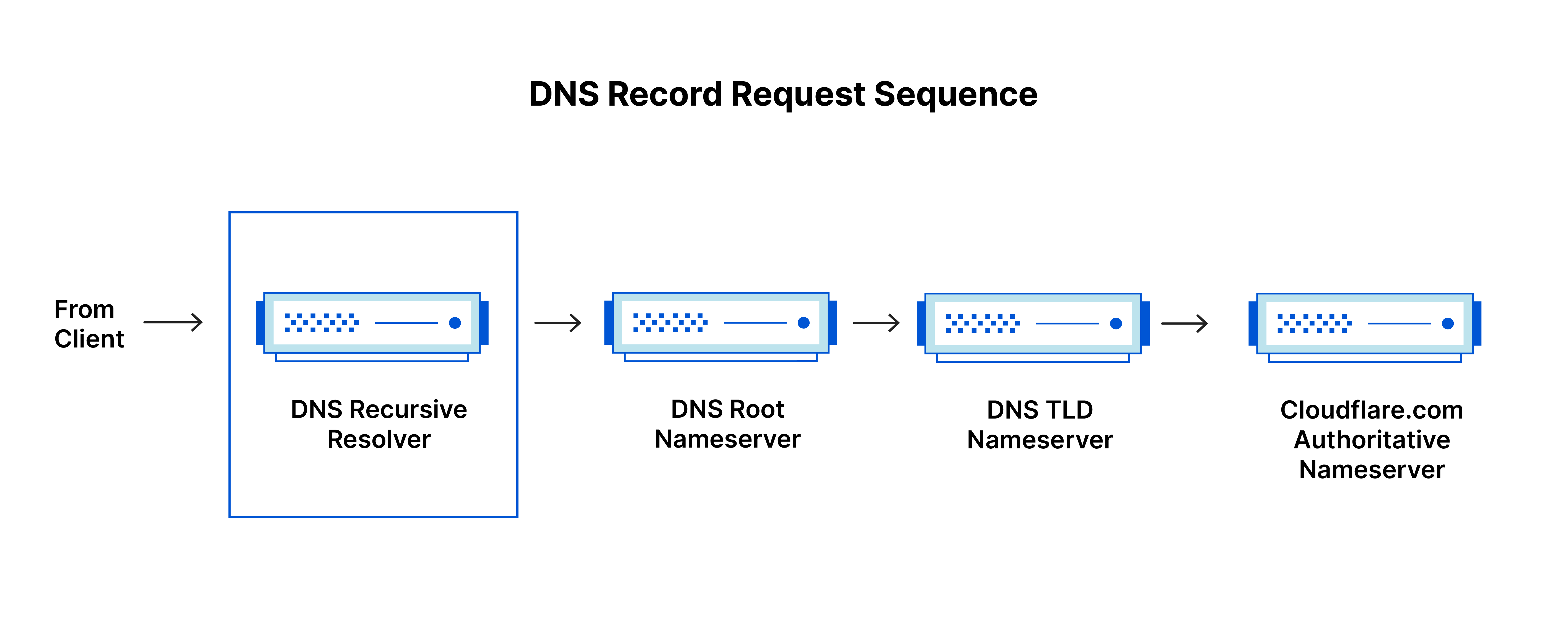
Authoritative DNS server
Put simply, an authoritative DNS server is a server that actually holds, and is responsible for, DNS resource records. This is the server at the bottom of the DNS lookup chain that will respond with the queried resource record, ultimately allowing the web browser making the request to reach the IP address needed to access a website or other web resources. An authoritative nameserver can satisfy queries from its own data without needing to query another source, as it is the final source of truth for certain DNS records.
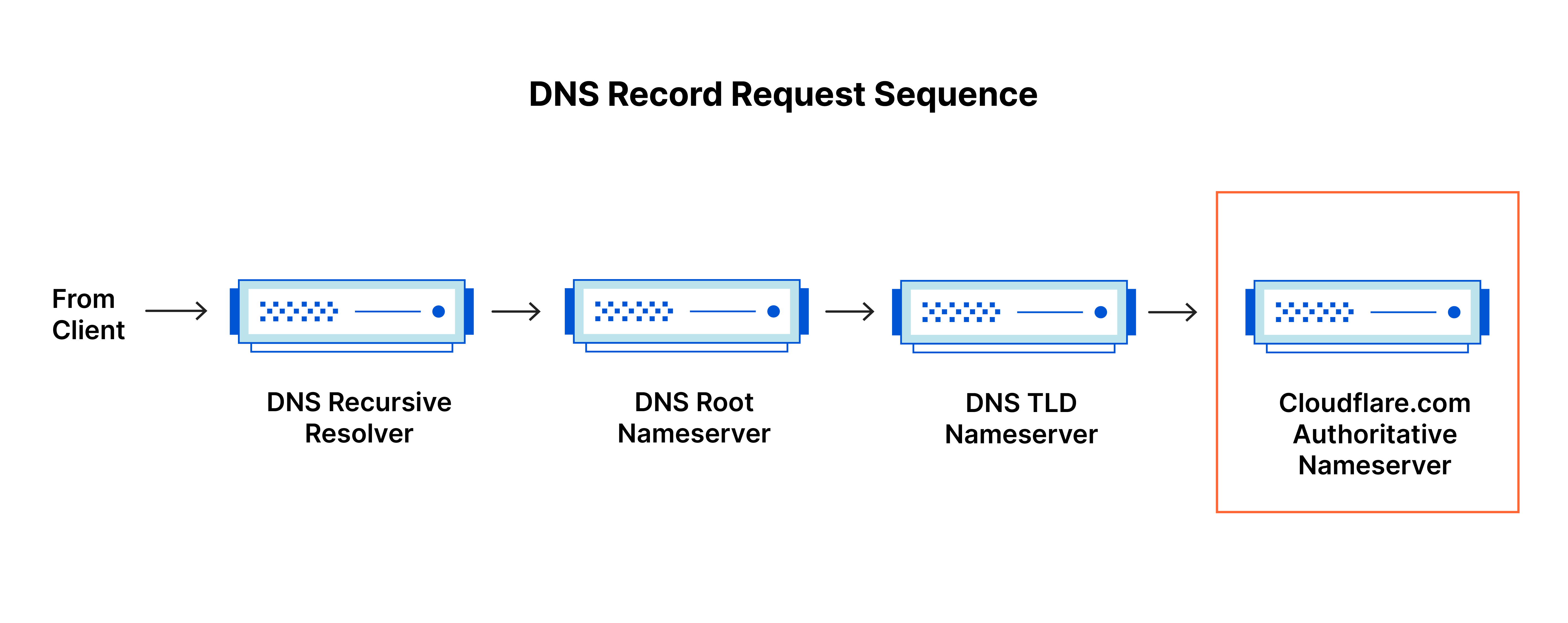
It’s worth mentioning that in instances where the query is for a subdomain such as foo.example.com or blog.cloudflare.com, an additional nameserver will be added to the sequence after the authoritative nameserver, which is responsible for storing the subdomain’s CNAME record.
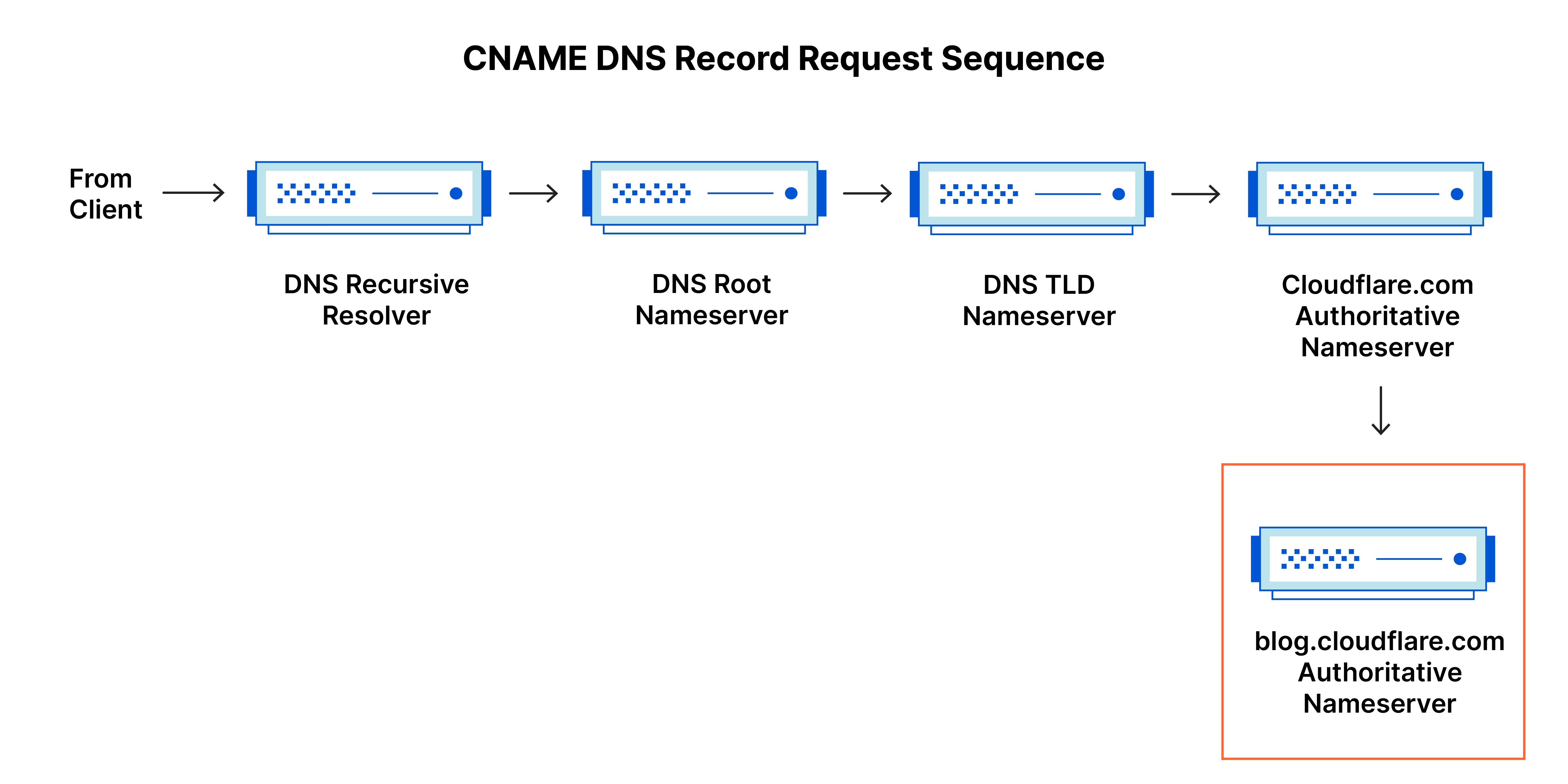
There is a key difference between many DNS services and the one that Cloudflare provides. Different DNS recursive resolvers such as Google DNS, OpenDNS, and providers like Comcast all maintain data center installations of DNS recursive resolvers. These resolvers allow for quick and easy queries through optimized clusters of DNS-optimized computer systems, but they are fundamentally different than the nameservers hosted by Cloudflare.
Cloudflare maintains infrastructure-level nameservers that are integral to the functioning of the Internet. One key example is the f-root server network which Cloudflare is partially responsible for hosting. The F-root is one of the root level DNS nameserver infrastructure components responsible for the billions of Internet requests per day. Our Anycast network puts us in a unique position to handle large volumes of DNS traffic without service interruption.
What are the steps in a DNS lookup?
For most situations, DNS is concerned with a domain name being translated into the appropriate IP address. To learn how this process works, it helps to follow the path of a DNS lookup as it travels from a web browser, through the DNS lookup process, and back again. Let's take a look at the steps.
Note: Often DNS lookup information will be cached either locally inside the querying computer or remotely in the DNS infrastructure. There are typically 8 steps in a DNS lookup. When DNS information is cached, steps are skipped from the DNS lookup process which makes it quicker. The example below outlines all 8 steps when nothing is cached.
The 8 steps in a DNS lookup:
- A user types ‘example.com’ into a web browser and the query travels into the Internet and is received by a DNS recursive resolver.
- The resolver then queries a DNS root nameserver (.).
- The root server then responds to the resolver with the address of a Top Level Domain (TLD) DNS server (such as .com or .net), which stores the information for its domains. When searching for example.com, our request is pointed toward the .com TLD.
- The resolver then makes a request to the .com TLD.
- The TLD server then responds with the IP address of the domain’s nameserver, example.com.
- Lastly, the recursive resolver sends a query to the domain’s nameserver.
- The IP address for example.com is then returned to the resolver from the nameserver.
- The DNS resolver then responds to the web browser with the IP address of the domain requested initially.
- The browser makes a HTTP request to the IP address.
- The server at that IP returns the webpage to be rendered in the browser (step 10).
Once the 8 steps of the DNS lookup have returned the IP address for example.com, the browser is able to make the request for the web page:
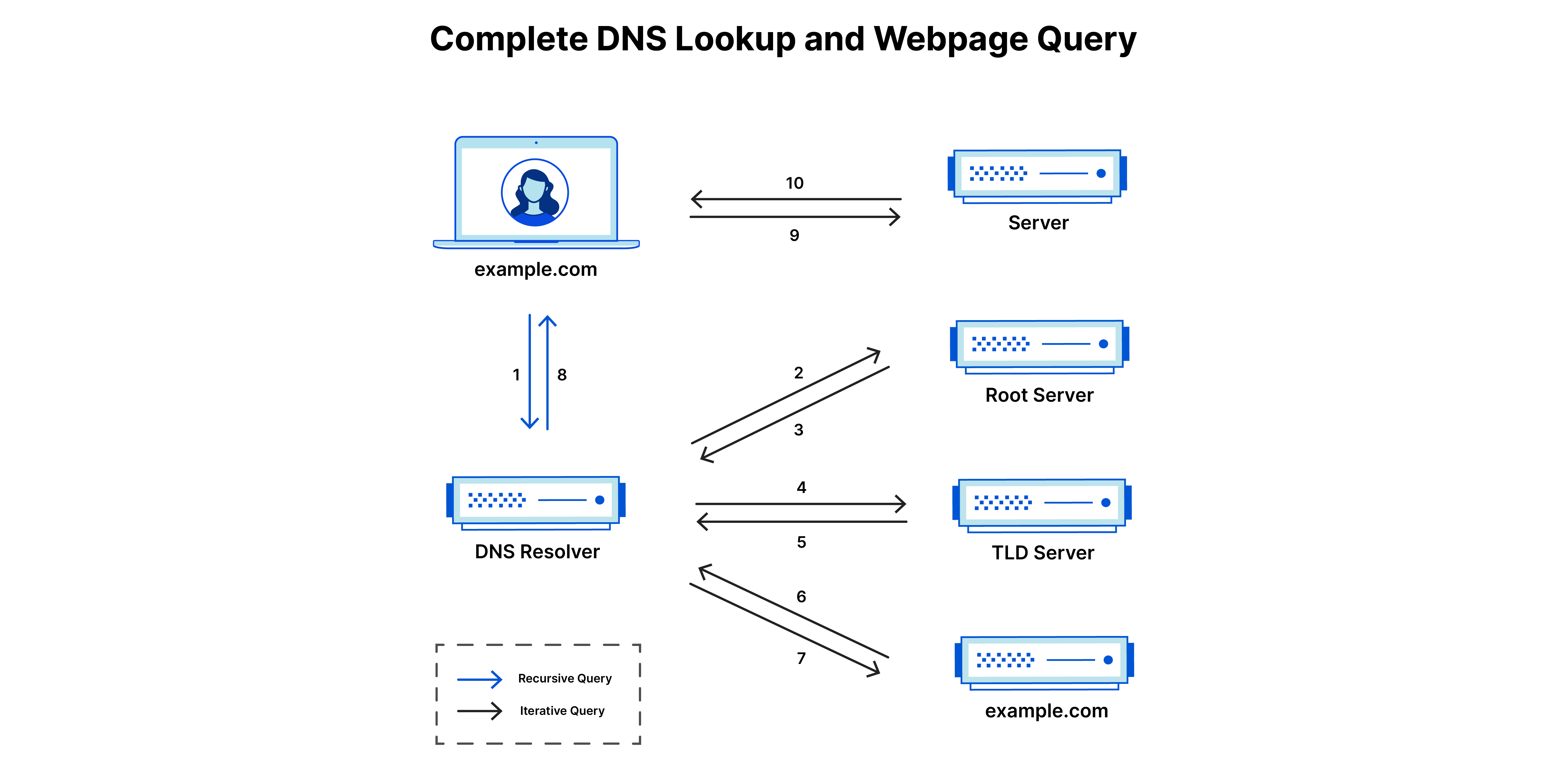
What is a DNS resolver?
The DNS resolver is the first stop in the DNS lookup, and it is responsible for dealing with the client that made the initial request. The resolver starts the sequence of queries that ultimately leads to a URL being translated into the necessary IP address.
Note: A typical uncached DNS lookup will involve both recursive and iterative queries.
It's important to differentiate between a recursive DNS query and a recursive DNS resolver. The query refers to the request made to a DNS resolver requiring the resolution of the query. A DNS recursive resolver is the computer that accepts a recursive query and processes the response by making the necessary requests.
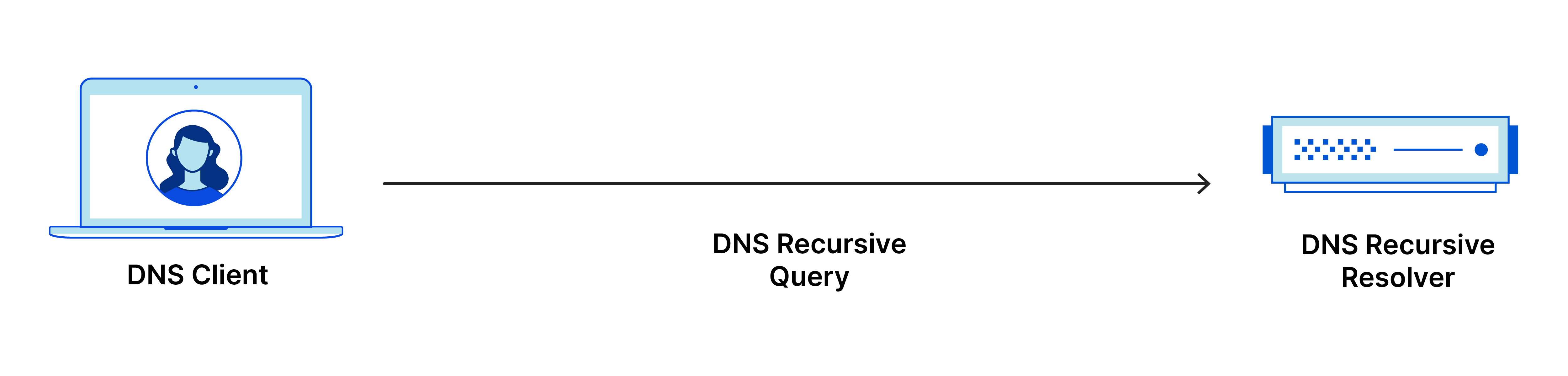
What are the types of DNS queries?
In a typical DNS lookup three types of queries occur. By using a combination of these queries, an optimized process for DNS resolution can result in a reduction of distance traveled. In an ideal situation cached record data will be available, allowing a DNS name server to return a non-recursive query.
3 types of DNS queries:
- Recursive query - In a recursive query, a DNS client requires that a DNS server (typically a DNS recursive resolver) will respond to the client with either the requested resource record or an error message if the resolver can't find the record.
- Iterative query - in this situation the DNS client will allow a DNS server to return the best answer it can. If the queried DNS server does not have a match for the query name, it will return a referral to a DNS server authoritative for a lower level of the domain namespace. The DNS client will then make a query to the referral address. This process continues with additional DNS servers down the query chain until either an error or timeout occurs.
- Non-recursive query - typically this will occur when a DNS resolver client queries a DNS server for a record that it has access to either because it's authoritative for the record or the record exists inside of its cache. Typically, a DNS server will cache DNS records to prevent additional bandwidth consumption and load on upstream servers.
What is DNS caching? Where does DNS caching occur?
The purpose of caching is to temporarily stored data in a location that results in improvements in performance and reliability for data requests. DNS caching involves storing data closer to the requesting client so that the DNS query can be resolved earlier and additional queries further down the DNS lookup chain can be avoided, thereby improving load times and reducing bandwidth/CPU consumption. DNS data can be cached in a variety of locations, each of which will store DNS records for a set amount of time determined by a time-to-live (TTL).
Browser DNS caching
Modern web browsers are designed by default to cache DNS records for a set amount of time. The purpose here is obvious; the closer the DNS caching occurs to the web browser, the fewer processing steps must be taken in order to check the cache and make the correct requests to an IP address. When a request is made for a DNS record, the browser cache is the first location checked for the requested record.
In Chrome, you can see the status of your DNS cache by going to chrome://net-internals/#dns.
Operating system (OS) level DNS caching
The operating system level DNS resolver is the second and last local stop before a DNS query leaves your machine. The process inside your operating system that is designed to handle this query is commonly called a “stub resolver” or DNS client. When a stub resolver gets a request from an application, it first checks its own cache to see if it has the record. If it does not, it then sends a DNS query (with a recursive flag set), outside the local network to a DNS recursive resolver inside the Internet service provider (ISP).
When the recursive resolver inside the ISP receives a DNS query, like all previous steps, it will also check to see if the requested host-to-IP-address translation is already stored inside its local persistence layer.
The recursive resolver also has additional functionality depending on the types of records it has in its cache:
- If the resolver does not have the A records, but does have the NS records for the authoritative nameservers, it will query those name servers directly, bypassing several steps in the DNS query. This shortcut prevents lookups from the root and .com nameservers (in our search for example.com) and helps the resolution of the DNS query occur more quickly.
- If the resolver does not have the NS records, it will send a query to the TLD servers (.com in our case), skipping the root server.
- In the unlikely event that the resolver does not have records pointing to the TLD servers, it will then query the root servers. This event typically occurs after a DNS cache has been purged.
Multipurpose Internet Mail Extension (MIME) Protocol
Multipurpose Internet Mail Extension (MIME) is a standard that was proposed by Bell Communications in 1991 in order to expand the limited capabilities of email.
MIME is a kind of add-on or a supplementary protocol that allows non-ASCII data to be sent through SMTP. It allows the users to exchange different kinds of data files on the Internet: audio, video, images, application programs as well.
Why do we need MIME?
Limitations of Simple Mail Transfer Protocol (SMTP):
- SMTP has a very simple structure
- Its simplicity however comes with a price as it only sends messages in NVT 7-bit ASCII format.
- It cannot be used for languages that do not support 7-bit ASCII format such as French, German, Russian, Chinese and Japanese, etc. so it cannot be transmitted using SMTP. So, in order to make SMTP more broad, we use MIME.
- It cannot be used to send binary files or video or audio data.
Purpose and Functionality of MIME –
Growing demand for Email Messages as people also want to express themselves in terms of Multimedia. So, MIME another email application is introduced as it is not restricted to textual data.
MIME transforms non-ASCII data at the sender side to NVT 7-bit data and delivers it to the client SMTP. The message on the receiver side is transferred back to the original data. As well as we can send video and audio data using MIME as it transfers them also in 7-bit ASCII data.
Simple Mail Transfer Protocol (SMTP)
Email is emerging as one of the most valuable services on the internet today. Most internet systems use SMTP as a method to transfer mail from one user to another. SMTP is a push protocol and is used to send the mail whereas POP (post office protocol) or IMAP (internet message access protocol) is used to retrieve those emails at the receiver’s side.
SMTP Fundamentals
SMTP is an application layer protocol. The client who wants to send the mail opens a TCP connection to the SMTP server and then sends the mail across the connection. The SMTP server is an always-on listening mode. As soon as it listens for a TCP connection from any client, the SMTP process initiates a connection through port 25. After successfully establishing a TCP connection the client process sends the mail instantly.
SMTP Protocol
The SMTP model is of two types:
- End-to-end method
- Store-and-forward method
The end-to-end model is used to communicate between different organizations whereas the store and forward method is used within an organization. An SMTP client who wants to send the mail will contact the destination’s host SMTP directly, in order to send the mail to the destination. The SMTP server will keep the mail to itself until it is successfully copied to the receiver’s SMTP.
The client SMTP is the one that initiates the session so let us call it the client-SMTP and the server SMTP is the one that responds to the session request so let us call it receiver-SMTP. The client-SMTP will start the session and the receiver SMTP will respond to the request.
Model of SMTP System
In the SMTP model user deals with the user agent (UA), for example, Microsoft Outlook, Netscape, Mozilla, etc. In order to exchange the mail using TCP, MTA is used. The user sending the mail doesn’t have to deal with MTA as it is the responsibility of the system admin to set up a local MTA. The MTA maintains a small queue of mail so that it can schedule repeat delivery of mail in case the receiver is not available. The MTA delivers the mail to the mailboxes and the information can later be downloaded by the user agents.
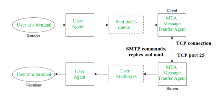
SMTP Model
Components of SMTP
- Mail User Agent (MUA)
- Mail Submission Agent (MSA)
- Mail Transfer Agent (MTA)
- Mail Delivery Agent (MDA)
1. Mail User Agent (MUA): It is a computer application that helps you in sending and retrieving mail. It is responsible for creating email messages for transfer to the mail transfer agent(MTA).
2. Mail Submission Agent (MSA): It is a computer program that basically receives mail from a Mail User Agent(MUA) and interacts with the Mail Transfer Agent(MTA) for the transfer of the mail.
3. Mail Transfer Agent(MTA): It is basically software that has the work to transfer mail from one system to another with the help of SMTP.
4. Mail Delivery Agent(MDA): A mail Delivery agent or Local Delivery Agent is basically a system that helps in the delivery of mail to the local system.
Working of SMTP
1. Communication between the sender and the receiver :
The sender’s user agent prepares the message and sends it to the MTA. The MTA’s responsibility is to transfer the mail across the network to the receiver’s MTA. To send mail, a system must have a client MTA, and to receive mail, a system must have a server MTA.
2. Sending Emails:
Mail is sent by a series of request and response messages between the client and the server. The message which is sent across consists of a header and a body. A null line is used to terminate the mail header and everything after the null line is considered the body of the message, which is a sequence of ASCII characters. The message body contains the actual information read by the receipt.
3. Receiving Emails:
The user agent on the server-side checks the mailboxes at a particular time of intervals. If any information is received, it informs the user about the mail. When the user tries to read the mail it displays a list of emails with a short description of each mail in the mailbox. By selecting any of the mail users can view its contents on the terminal.
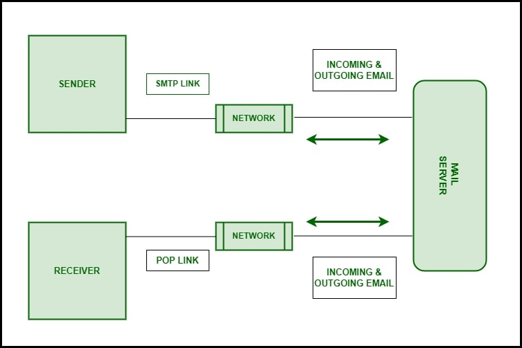
Working of SMTP
Some SMTP Commands
- HELO – Identifies the client to the server, fully qualified domain name, only sent once per session
- MAIL – Initiate a message transfer, the fully qualified domain of the originator
- RCPT – Follows MAIL, identifies an addressee, typically the fully qualified name of the addressee, and for multiple addressees use one RCPT for each addressee
- DATA – send data line by line
For more, you can refer to SMTP Commands.
Difference between SMTP and Extended SMTP
Extended STMP is an extended version of SMTP. Extended SMTP is a set of protocols for sending and receiving electronic messages on the internet. First, Email is sent from sender to sender-server through ESTMP and from sender-server to receiver-server on the internet through ESTMP. ESMTP follows the same protocols as SMTP. It adds more functionality, security, and authentication than SMTP.
Let’s see some basic differences between them.
| SMTP | Extended SMTP |
|---|---|
| Users were not verified in SMTP as a result of massive-scale scam emails being sent. | In Extended SMTP, authentication of the sender is done. |
| We cannot attach a Multimedia file in SMTP directly without the help of MMIE. | We can directly attach Multimedia FIle in ESMTP. |
| We cannot reduce the size of the email in Extended SMTP. | We can reduce the size of the email in Extended SMTP. |
| SMTP clients open transmission with the command HELO. | The main identification feature for ESMTP clients is to open a transmission with the command EHLO (Extended HELLO). |
Advantages of SMTP
- If necessary, the users can have a dedicated server.
- It allows for bulk mailing.
- Low cost and wide coverage area.
- Offer choices for email tracking.
- Reliable and prompt email delivery.
Disadvantages of SMTP
- SMTP’s common port can be blocked by several firewalls.
- SMTP security is a bigger problem.
- Its simplicity restricts how useful it can be.
- Just 7-bit ASCII characters can be used.
- If a message is longer than a certain length, SMTP servers may reject the entire message.
- Delivering your message will typically involve additional back-and-forth processing between servers, which will delay sending and raise the likelihood that it won’t be sent.
What is World Wide Web (WWW, W3)?
The World Wide Web -- also known as the web, WWW or W3 -- refers to all the public websites or pages that users can access on their local computers and other devices through the internet. These pages and documents are interconnected by means of hyperlinks that users click on for information. This information can be in different formats, including text, images, audio and video.
The term World Wide Web isn't synonymous with the internet. Rather, the World Wide Web is part of the internet.
How does the World Wide Web work?
Paving the way for an internet revolution that has transformed the world in only three decades, the World Wide Web consists of multiple components that enable users to access various resources, documents and web pages on the internet. Thus, the WWW is like a vast electronic book whose pages are stored or hosted on different servers worldwide.
These pages are the primary component or building blocks of the WWW and are linked through hyperlinks, which provide access from one specific spot in a hypertext or hypermedia document to another spot within that document or a different one. Hyperlinks are another defining concept of the WWW and provide its identity as a collection of interconnected documents
The Hypertext Transfer Protocol (HTTP) is another key component of the WWW. It enables users to access web pages by standardizing communications and data transfer between the internet's servers and clients.
Web browser evolution and the growth of the World Wide Web
Berners-Lee and his team developed a text-based web browser that was released in early 1992. However, it took the release of the more user-friendly Mosaic browser in 1993 to kickstart the rapid acceptance and adoption of the WWW. Mosaic provided a point-and-click graphical interface that people had been using in personal computers for a few years. This familiarity increased public interest in WWW and led to its rapid growth all over the world.
Entrepreneur and software engineer Marc Andreessen and others developed Mosaic in the United States. They also developed the Netscape Navigator browser that quickly became the dominant browser in 1994, until it was displaced by Microsoft's Internet Explorer in 1995. IE dominated the web browser space until it was challenged by browsers like Mozilla Firefox -- released in 2004 -- and Google Chrome -- released in 2008. In 2015, Microsoft discontinued IE and replaced it with the Microsoft Edge browser.
What will Web 3.0 look like compared to Web 1.0 and 2.0?
The World Wide Web continues to evolve. The first generation of the Web, Web 1.0, which Berners-Lee originally defined in 1989, had no video content and a page format similar to that of a printed page. Web 1.0 was primarily static and focused on providing information.
Around the beginning of the 21st century, Web 2.0 ushered in a new era that was more interactive and dynamic than its predecessor and focused on user collaboration, universal network connectivity and communications channels. As smartphones, mobile internet access and social networks spurred the growth of Web 2.0, applications -- such as Airbnb, TikTok, Twitter and Uber -- which increased online interactivity and utility, became increasingly popular.
With a lofty goal of creating more intelligent, connected and open websites, Web 3.0 is still in its infancy and has yet to be defined fully. Unlike Web 2.0, which includes applications and websites that entail user-generated content, Web 3.0 is expected to be fully decentralized; this places content creation in the hands of the creators rather than platform owners.
URL: Uniform Resource Locator
URL stands for Uniform Resource Locator. It is the address of a resource, which can be a specific webpage or a file, on the internet. It is also known as web address when it is used with http. It was created in 1994 by Tim Berners-Lee. URL is a specific character string that is used to access data from the World Wide Web. It is a type of URI (Uniform Resource Identifier).
Every URL contains the following information:
- The scheme name or protocol.
- A colon, two slashes.
- A host, normally called a domain name but sometimes as a literal IP address.
- A colon followed by a port number.
- Full path of the resource.
The URL of a web page is displayed above on the page in the address bar. A typical URL looks like this:
http://www.javatpoint.com/full-form
The above URL contains:
- protocol: http
- host or domain: www.javatpoint.com
- Path of the resource: /full-form
A URL can be entered manually by typing it in the address bar of your web browser. If the URL does not contain a valid server, a browser may display a "Server not found" error and if the path in the URL is incorrect, the browser may display a "404 error". A URL does not contain spaces and uses forward slashes to represent different directories. So, dashes and underscores are used separate the words of a web address. 
What is URI
URI stands for Uniform Resource Identifier. It is a generic term for all the name and addresses which show objects on the World Wide Web. It is generally a sequence of characters which identifies a logical resource or the name and location of a file or resource in a uniform format.
What is Symmetric Key Algorithms?
Symmetric key algorithms are a type of cryptographic technique that uses a shared secret key for both encryption and decryption. This means that the same key is used to encode and decode the message. Symmetric key algorithms are generally faster and more efficient than asymmetric key algorithms, but they require that the sender and receiver of a message share a secret key.
Here are some of the basic principles of symmetric key algorithms −
The same key is used for both encryption and decryption − In symmetric key algorithms, the same key is used to both encrypt and decrypt the message. This means that the sender and receiver of a message must share the same secret key in order to communicate securely.
Symmetric key algorithms are faster and more efficient than asymmetric key algorithms − Symmetric key algorithms are generally faster and more efficient than asymmetric key algorithms, as they do not require the use of complex mathematical operations such as exponentiation. This makes them well-suited for applications that require fast encryption and decryption, such as securing communication over the internet.
Symmetric key algorithms are less secure than asymmetric key algorithms − While symmetric key algorithms are generally faster and more efficient than asymmetric key algorithms, they are also less secure. This is because the same key is used for both encryption and decryption, which means that if the key is compromised, the security of the entire system is compromised.
Overall, symmetric key algorithms are an important type of cryptographic technique that are used to secure communication and protect data. While they are generally faster and more efficient than asymmetric key algorithms, they are also less secure and require that the sender and receiver of a message share a secret key.
Cryptographic Strength of Symmetric Algorithms
The cryptographic strength of a symmetric key algorithm refers to its ability to resist attacks and protect the confidentiality of the information it is used to encrypt. The cryptographic strength of a symmetric key algorithm is determined by a variety of factors, including −
Key size − The size of the key used in a symmetric key algorithm is a major determinant of its cryptographic strength. In general, the larger the key size, the stronger the algorithm.
Block size − The block size of a symmetric key algorithm refers to the size of the blocks of data that are encrypted and decrypted using the algorithm. A larger block size can increase the cryptographic strength of the algorithm.
Number of rounds − The number of rounds in a symmetric key algorithm refers to the number of times that the encryption and decryption process is repeated. A larger number of rounds can increase the cryptographic strength of the algorithm.
Resistance to attacks − The resistance of a symmetric key algorithm to attacks, such as brute-force attacks or differential cryptanalysis, is another factor that determines its cryptographic strength. Algorithms that are resistant to these types of attacks are generally considered to be stronger.
Overall, the cryptographic strength of a symmetric key algorithm is determined by a combination of these and other factors. Stronger algorithms are generally more resistant to attacks and more effective at protecting the confidentiality of the information they are used to encrypt.
Types of Symmetric Key Algorithms
There are several different types of symmetric key algorithms, including −
Block ciphers − Block ciphers are symmetric key algorithms that operate on fixed-size blocks of data and use a secret key to encrypt and decrypt the data. Examples of block ciphers include the Advanced Encryption Standard (AES) and Blowfish.
Stream ciphers − Stream ciphers are symmetric key algorithms that operate on a stream of data and use a secret key to encrypt and decrypt the data. Stream ciphers are generally faster and more efficient than block ciphers, but they are also generally considered to be less secure.
Feistel ciphers − Feistel ciphers are a type of block cipher that are based on a structure known as a Feistel network. They are widely used in symmetric key algorithms and are known for their efficiency and ease of implementation.
Substitution-permutation ciphers − Substitution-permutation ciphers are a type of block cipher that use both substitution and permutation operations to encrypt and decrypt data. They are known for their strong cryptographic properties and are used in many modern symmetric key algorithms.
Overall, there are many different types of symmetric key algorithms, each with its own unique characteristics and strengths. Symmetric key algorithms are an important type of cryptographic technique that are used to secure communication and protect data.
Cryptography
It is a technique of writing in a secret code which is in an unreadable format to the third parties. Plaintext indicates the data which is in the readable format and also which is not encrypted.
The plaintext is converted into cipher text which is in the format of unreadable with the help of the encryption and again it is to be converted into plaintext with the help of the decryption. Both the encryption and the decryption are done with the help of the scheme of the cryptography.
Functions of cryptography
The functions of cryptography are as follows −
- Confidentiality
- Integrity
- Authenticity
- Non-repudiation
- Symmetric algorithm
Symmetric Algorithm
The symmetric algorithm is explained below in stepwise manner −
Step 1 − Symmetric algorithm is referred to as a secret key algorithm. For encrypting and decrypting data, the same key is used on both sides which results in a faster and simpler one.
Step 2 − Both the sender and the receiver must use the same key for encryption and decryption. That is, with the help of the public key the plain text is converted into cipher text and it has been sent to the destination from the source, and with the help of the same key, which has been used by the sender, must be used by the receiver for decrypting the cipher text into the plaintext.
Step 3 − So for decrypting and encrypting data, both the sender and the receiver must know about the public key which is referred to as a secret key.
Step 4 − Stream Ciphers always work on one bit at a time. For encrypting data the same key is used in stream cipher.
Step 5 − Block Ciphers always work on one block at a time. In stream cipher, for encrypting a block of data a different key is used.
Public Key Algorithm
The public key algorithm is explained below in stepwise manner −
Step 1 − In the Public key algorithm, for data encryption and data decryption separate keys have been used which results in complex.
Step 2 − It normally uses one key for data encryption from the plaintext and sent to the destination.
Step 3 − At the receiver side, the receiver uses another key separately for decrypting the encrypted data to the plaintext. So, here two has been separated by both the source and destination which cannot be identified by the parties.
Digital signature
It is an electronic document, which provides the authority certification which contains the digital signature. It helps in verifying a person's identity with the help of the public key. One way hash value is to be created for the digital signature and for encrypting the hash value a private key is used which results in unique value. Hence, the combination of hash value which is encrypted, and the hashing algorithm together create a Digital Signature, where the functions of cryptography are settled.
RSA − It refers to Rivest-Shamir-Adleman algorithm, which is being embedded with the SSL protocol for providing the secured communication over the network, in which the public key has been generated from the product of two large prime numbers which is 1024 or 2048 bit long.
Elliptic Curve Cryptography (ECC) − It is used as an alteration to the RSA algorithm in implementing the public key which results in small keys and it has been generated with the equation of the elliptic curve. It is more complex in breaking ECC because formulating the ECC algorithm is more complex than factoring the prime numbers and also the key size is small.


No comments:
Post a Comment